The TotalYmage application allows its users to create, modify and publish what we call environments; it becomes simple to create interactive scenes in 360° images of physical locations, as well as interactive navigation in 3D models, interactive dashboards and maps, and interactive presentations.
We will cover herebelow the editing tools and the functionnalities of the TotalYmage application.
Login Process
Each user has unique and personal credentials and should not share them with an other user.
If you don’t have credentials (usually login and password), please ask your administrator.
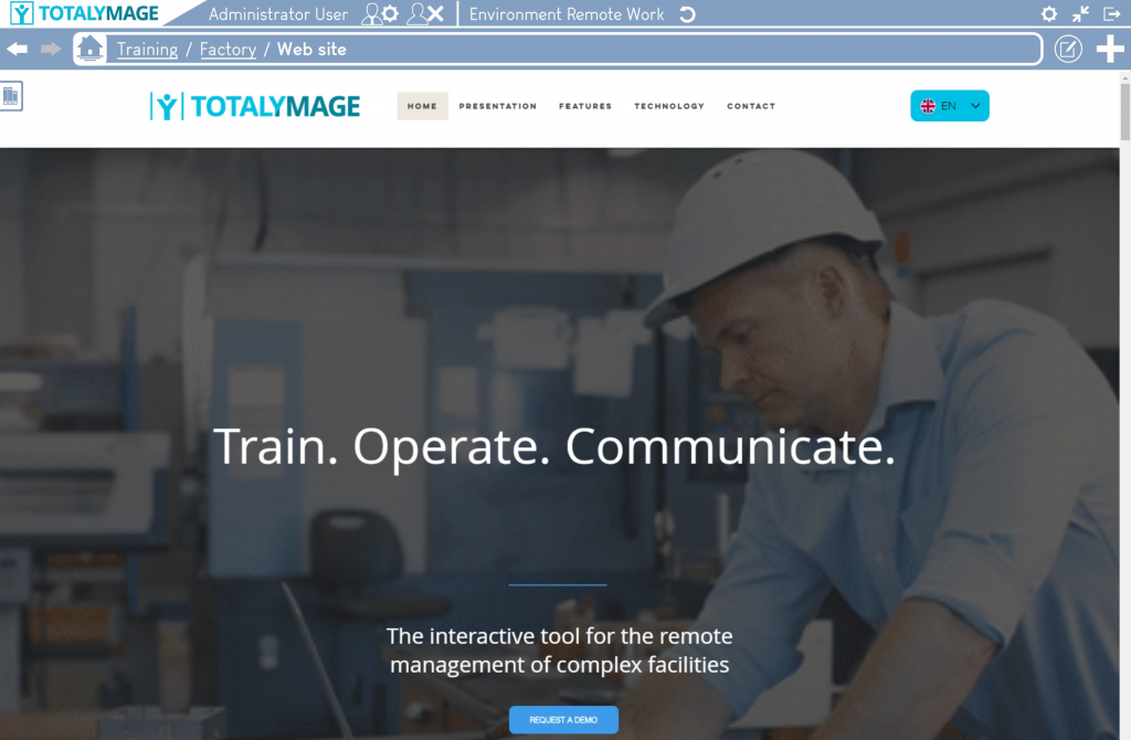
Upon launching the TotalYmage application in the applications section, the login page is displayed.
A user must enter her/his personal credentials in the corresponding text boxes in the login screen.
Usual credentials are the “Email address” and “Password”.
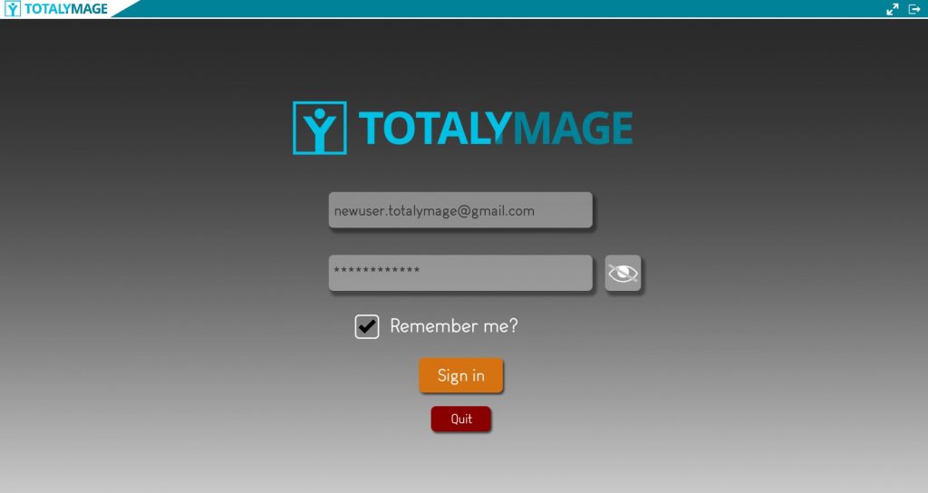
An online connection is needed for the authentication process to validate the user.
A company’s administrator may also give an offline right to a specific user. The user needs to login online to make this offline right effective, and then has the ability to connect offline for the time period defined for the company.
Other authentication processes may be put in place by the administrator of the company, using for example the Active Directory, SSO, MFA, physical security keys, or security tokens shared with third party applications.
This will always remain at the choice of the company to decide the authentication process.
Environment selection
An environment is a set of interactive projects, dashboards and presentations.
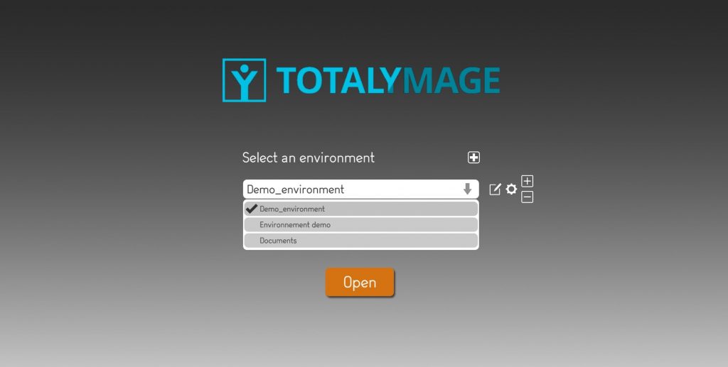
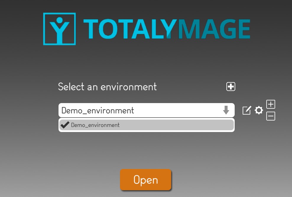
Upon login, the environments management page is displayed.
A user will see the environments list he has access rights on:
– environments he created on his computer locally
– environments whose creator gave the user the rights to access them
Please note that the visitor users don’t see the buttons to create or modify the environments.
They only see the buttons they can access in read only mode.
If the user just started to use the TotalYmage application, the environment list may be empty.
At all times a visitor user or an editor user can manage the list of environments to be displayed in the environments list.
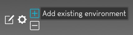
The user may add an existing environment to the environments list.
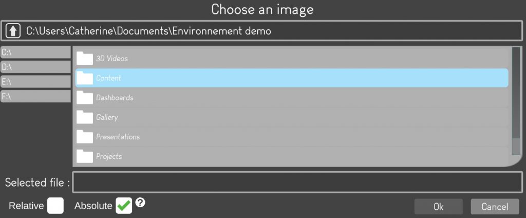
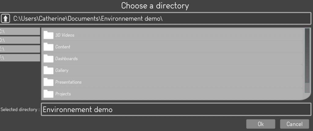
The user must click on the “+” to add an environment that is already stored on the local drive or an external drive, by browsing the directories selection.
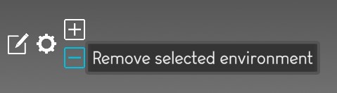
The user may select an environment from the list and click on the “-” to remove the selected environment.
The user may click on :
– the “remove” button to just remove the selected environment from the list of visible environments in the dropdown list.
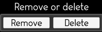
– the “delete” button to delete all files of the selected environment from the directory where they are stored. The environment will be deleted and the user will lose all the data.
If an environment is deleted, this is a soft delete. The environment has been transferred to a bin/ directory for a 1 day delay before permanent deletion.
A user may click on the “restore” button to retrieve the deleted environment and display it in the dropdown list.
If the environments list is not empty, the user can visualize the available environments and can select one of them from the list and open it.
Environment creation
An editor user can create a new environment in two ways:
– creating a new empty environment
– copying an existing environment
The user must write a name for the new environment.
The user must select the directory where the new environment will be created.
The user must select the creation mode between “New” and “Copy”.
Upon selecting “Copy” the user must choose the existing environment he wants to duplicate.
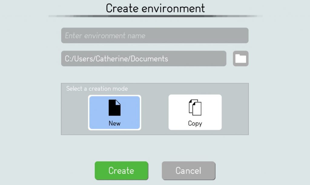
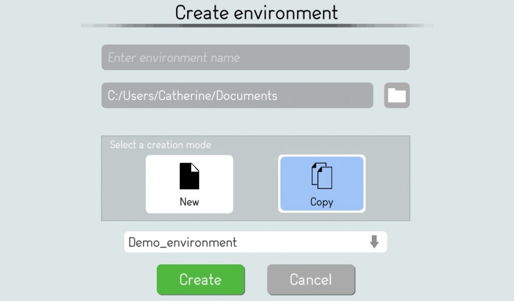
The user then starts the creation process of the environment by clicking on the “Create” button.
This opens the environment settings page whereby the user can define the configuration of the new environment.
If the user creates a new environment by copy of an existing one, the displayed settings are those of the copied environment.
The user can modify them before finalizing the creation by copy.
An editor user may change the default options before the creation of the environment.
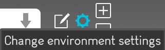
But an editor user can also change them afterwards by clicking on the “Change environment settings” button in the environments management page.
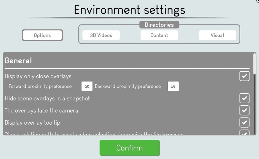
We review below all options of the environment settings page.
The editor user can display the 4 different tabs to update their options.
Options
Upon clicking on the “Options” button, different settings are available to the user to create and visualize the environment content.
General
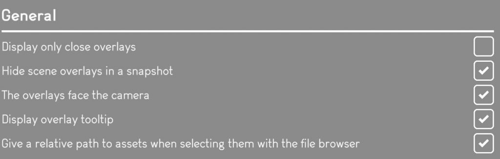
Display only close overlays

Uncheck the box for 3D overlays in a scene to be displayed at all times.
Users can see all overlays of the scene.
The overlays appear bigger if they are closer to the user.

Check the box for 3D overlays to be displayed only when the user is close to them when navigating in the scene.
Input the “Forward proximity preference” and the “Backward proximity preference” to define the range of images when the 3D overlays are displayed.
For example defining a 50 / 50 preference means a user will see the 3D overlays on a range of 100 consecutive images of the scene, centered on the 3D overlay position, 50 apart.
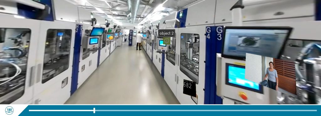
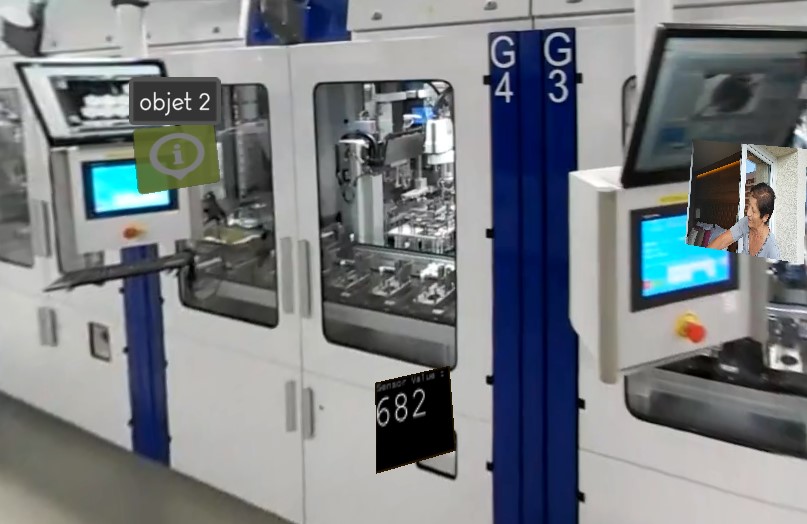
Hide scene overlays in a snapshot

Check the box for the users to only see the snapshot and its 2D overlays.


Uncheck the box to also see by transparency the 3D overlays of the scene.

The overlays face the camera

Check the box for the 3D overlays in a scene to always face the user.

Uncheck the box if you want by default to fix the orientation of the overlays in the scene.
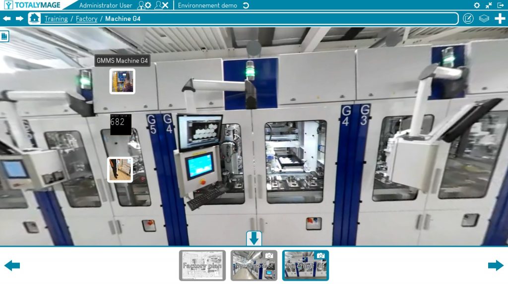
Display overlay tooltip
A tooltip is a comment that is displayed when the user points the mouse over an overlay or a button; or when the user touches an overlay or a button on a touch screen.
A tooltip is aimed at displaying the name of an overlay, and the instruction of a button.

Check the box to show the tooltip over a 3D overlay in a scene and a 2D overlay in a dashboard or snapshot or snapshot 360.
Users can see the name of the overlay when they point the mouse over the overlay or when they touch the overlay on a touch screen.

Uncheck the box to hide the tooltip over a 3D overlay in a scene and a 2D overlay in a dashboard or snapshot or snapshot 360.
No name will appear above the overlay upon pointing the mouse over the overlay or touching the overlay on a touch screen.
On the contrary to the tooltips of the overlays, the tooltips of the buttons in the application are always displayed when the user puts the mouse on a button; and when the user touches a button of the application on a touch screen.
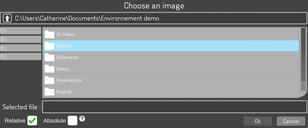
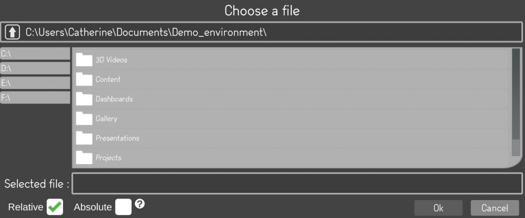
Give a relative path to assets when selecting them with the file browser
When editing a content of a 2D or 3D overlay an editor user must select the content type and select the content itself. Upon selecting the content, the editor user must define if the content will be accessed through an absolute path or a relative path.
An absolute path is a defined path to a directory, a server, that should be accessible to all users for them to access the content.
This option is used when users share content directories.
A relative path is an internal path within the environment to access the content locally.
The relative content is saved in the environment data to allow all users to access it even if they don’t share the same IT environment.
While an environment is downloaded, its data contains all needed content.

Check the box to have a relative path as the default option when defining the content of an overlay.

Uncheck the box to have an absolute path as the default option when defining the content of an overlay.
Upon selecting a specific content for an overlay, an editor user can modify the setting from the default option to the appropriate setting, for example from absolute to relative.
But this means that the content won’t be dynamic any longer because not linked to its source.
Alternatively, if the editor user modifies the setting of an overlay content from the relative default option to absolute, the content will be defined by its absolute path that some users may not be able to access.
Open overlay content inside a floating window
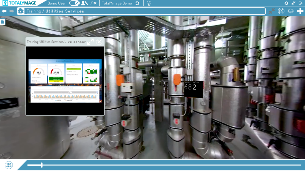
When double clicking on an overlay whose content is 2D (image, video, PDF, XL, Word, Powerpoint documents), therefore excluding 3D content (360° image, 360° video, live Immervision 360° video), a user can open the content in a floating window or in a full screen mode.
A floating window is a reduced window that can be moved on the screen and can be resized by dragging any of its sides.
It remains opened as the user navigates in the environment, opens other projects, scenes, dashboards, snapshots. It closes automatically if the user quits the environment.
The user can open other content and display several floating windows at the same time.
This option is designed to define the default for the size of the content display upon double clicking on the overlay.

Check the box to define the default to display the overlays content in a floating window. Upon double clicking on an overlay, a floating window displays the 2D content.
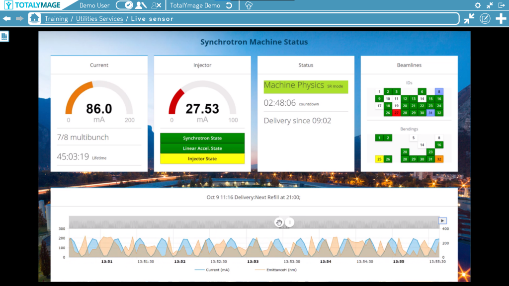
To display the content in a full screen window the user can at any time click on the Fullscreen mode button.

Uncheck the box to define the default to display the overlays content in a full screen window. Upon double clicking on an overlay, a full screen window displays the 2D content.
To display the content in a floating window the user can at any time click on the Window mode button.
Graphics
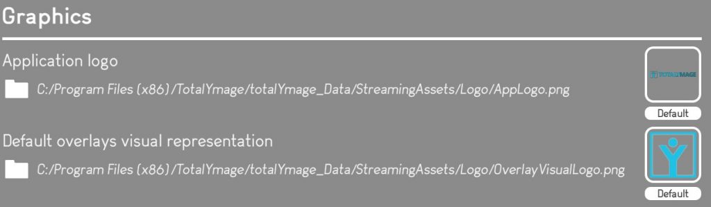
Application logo
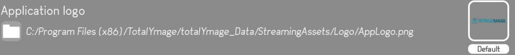
An editor user can modify the logo displayed in the TotalYmage application on the upper left corner.
A default logo is defined at the application level but each environment can have a different logo.
Hence an editor user can modify the default logo when creating or mofiying an environment.
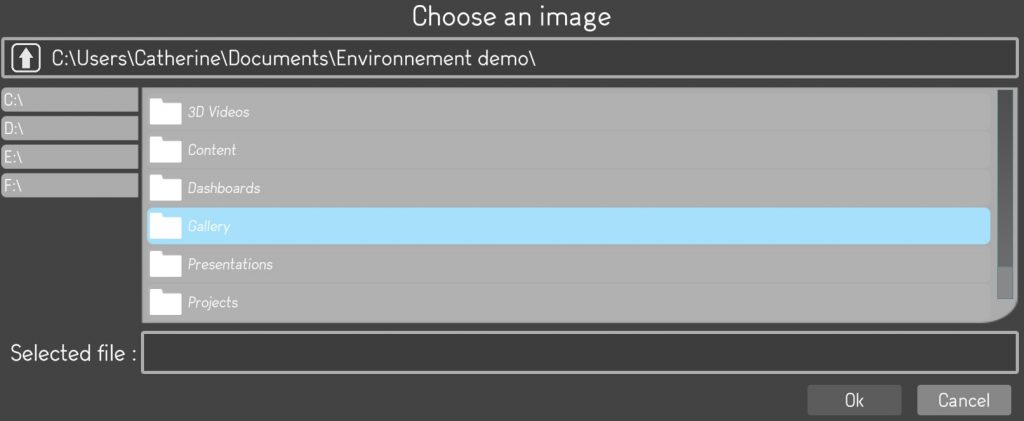
The editor user must select the logo file for the environment by browsing the directories and click on the “Ok” button.
The selected logo will become the logo for the environment.
For a company willing to use a single logo for all its environments, there is a way to make a logo the default one for all environments.
Each time a new environment will be created the displayed logo would be this default logo.
An Administrator user can set this default logo for all environments by renaming an image file to “Applogo” and by saving it to the following directory in the application files:
Hence the application to be deployed across all users in the company must be the one with this configuration.
Default overlays visual representation
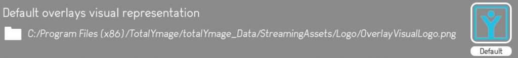
The overlay visual representation is the image displayed in the TotalYmage application when creating a 3D overlay in a scene or a 2D overlay in a dashboard, snapshot, snapshot 360, or in the content of a 3D or 2D overlay.
A default overlay visual representation is defined at the application level but each environment can have its own default overlay visual representation.
An editor user can modify the default overlay visual representation when creating an environment or at any time by modifying the environment settings.
The editor user must select the new overlay visual representation file for the environment by browsing the directories and click on the “Ok” button.
The selected overlay visual representation will become the new one for the environment.
For a company willing to use a single overlay visual representation for all its environments, there is a way to make one representation the default one for all environments.
Each time a new environment will be created by the users of the company the displayed representation for 3D or 2D overlays would be this default representation.
An Administrator user can set this default overlay visual representation for all environments by renaming an image file to “OverlayVisualLogo” and by saving it to the following directory in the application files:
Hence the application to be deployed across all users in the company must be the one with this configuration.
Display
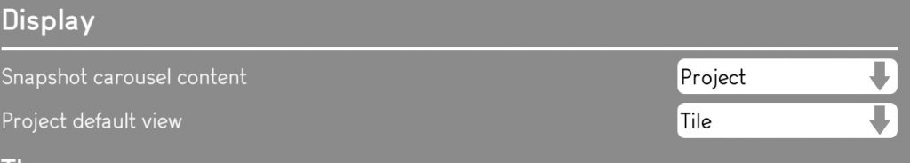
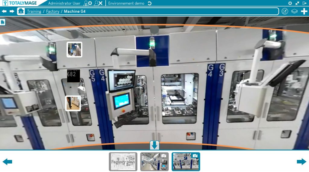
Snapshot carousel content
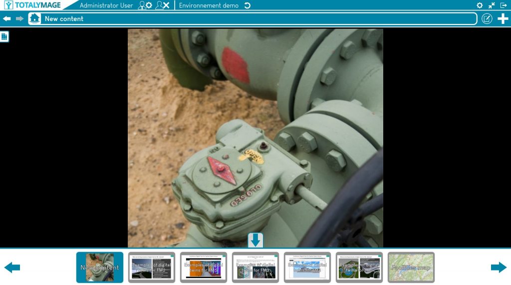
The carousel is a set of dashboards, snaphots and snapshots 360 that appears as a band of thumbnails at the bottom of the screen as soon as a user accesses any of its components.
An editor user can select one of the 3 options below to define the composition of the carousel.
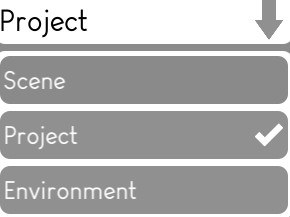
If the “Scene” option is selected, only the snapshots and snapshots 360 of the current scene will be displayed at the bottom of the screen.
If the “Project” option is selected, the projects dashboards, the snapshots and snapshots 360 of the scenes belonging to the current project will be displayed.
If the “Environment” option is selected, all dashboards, snapshots and snapshots 360 of any project and any scene in the current environment will be displayed.
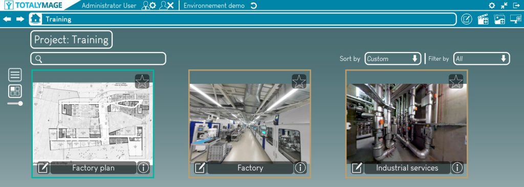
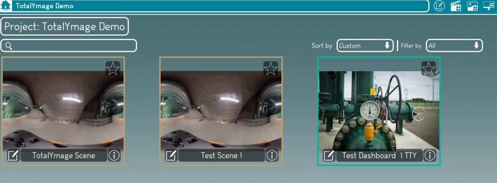
Project default view
This option allows to display project content of an environment in the TotalYmage application in two different ways.
Upon accessing a project, a user will see the dashboards and scenes, either in “List” or “Tile” mode.
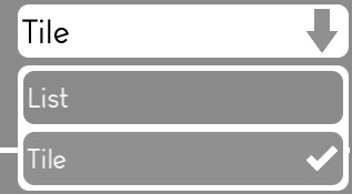
An editor user can choose the default option to display the project components of the environment.
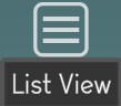
The editor user may choose the “List” option to see each component as a horizontal object in a list.
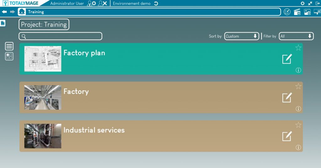
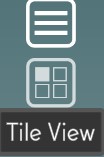
The editor user may choose the “Tile” option to see the components as thumbnails on the screen.
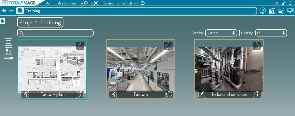
The display mode can be modified from the default option at any time by a user, by clicking on the “View List” or “View Tile” button of the project management page,
Themes
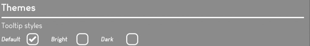
Tooltip styles

An editor user may choose a tooltip style among the three types below :
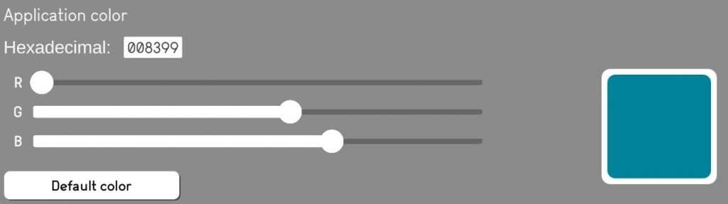
Application color
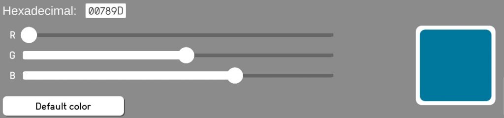
An editor user may modify the default color of the environment.
The editor user may enter the 6 characters Hexadecimal code.
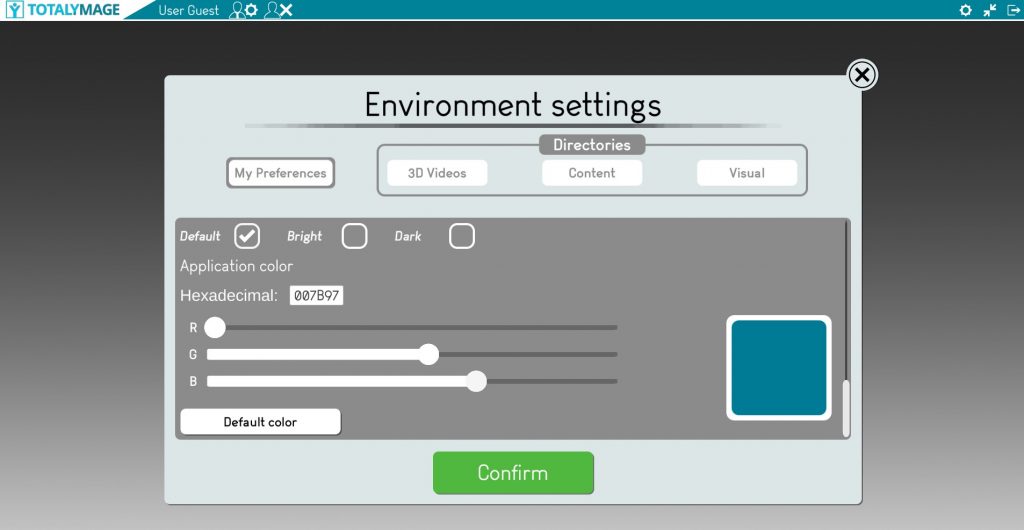
Or the editor user may slide the 3 color sliders to set the color of the environment.
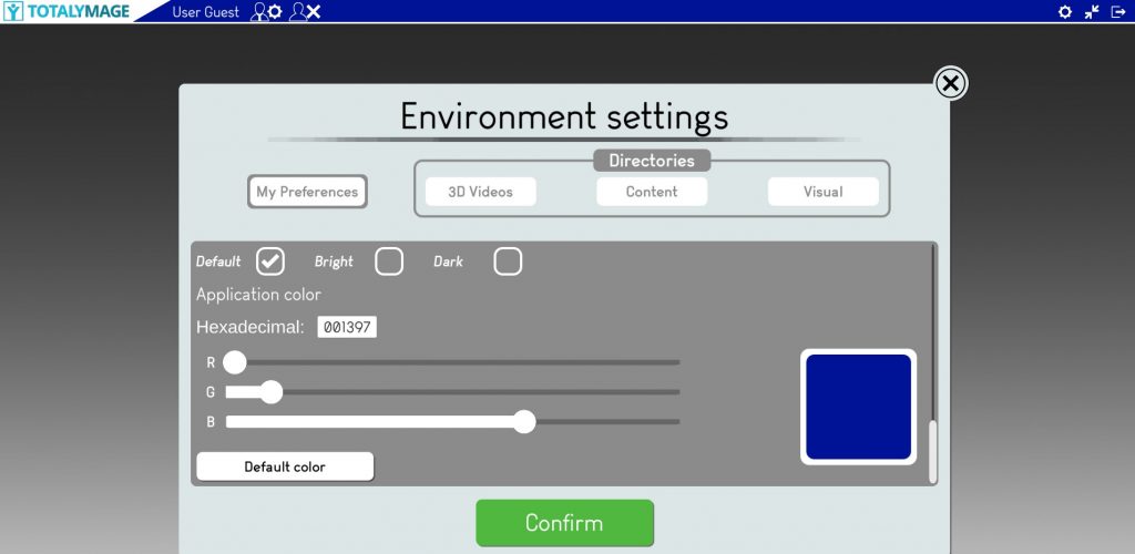
As a result, a scene will have a new color.
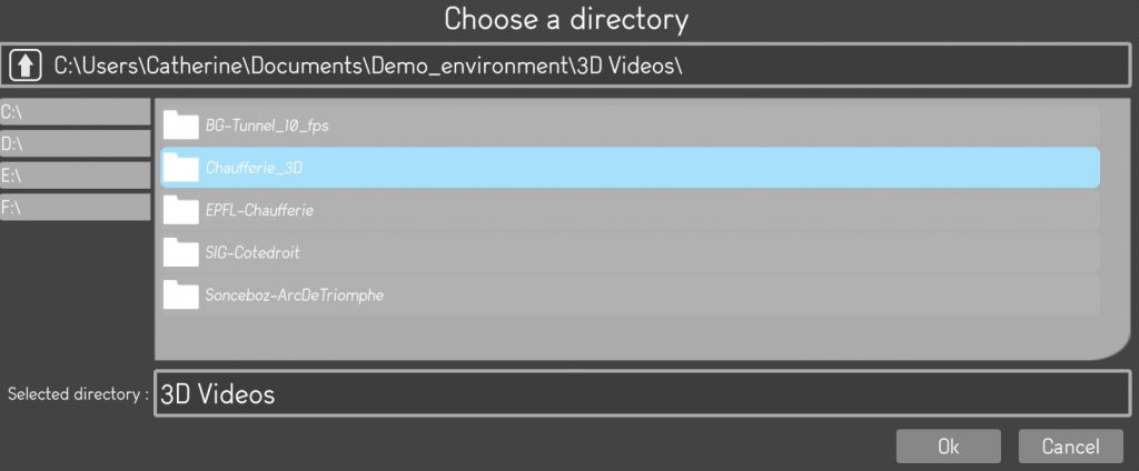
3D Videos
The 3D Videos section allows editing users to define the directory where all 3D videos will be stored and accessed from.
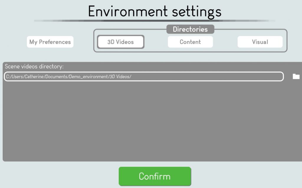
An editing user can define the exact path of the directory.
Upon opening an environment the 3D videos will be loaded by the application from the defined directory.
Directories for 3D videos can be located on the same computer or on external servers or external drives.
Content
Upon creating or editing a 2D or 3D overlay an editing user will select a type of content and the content itself.
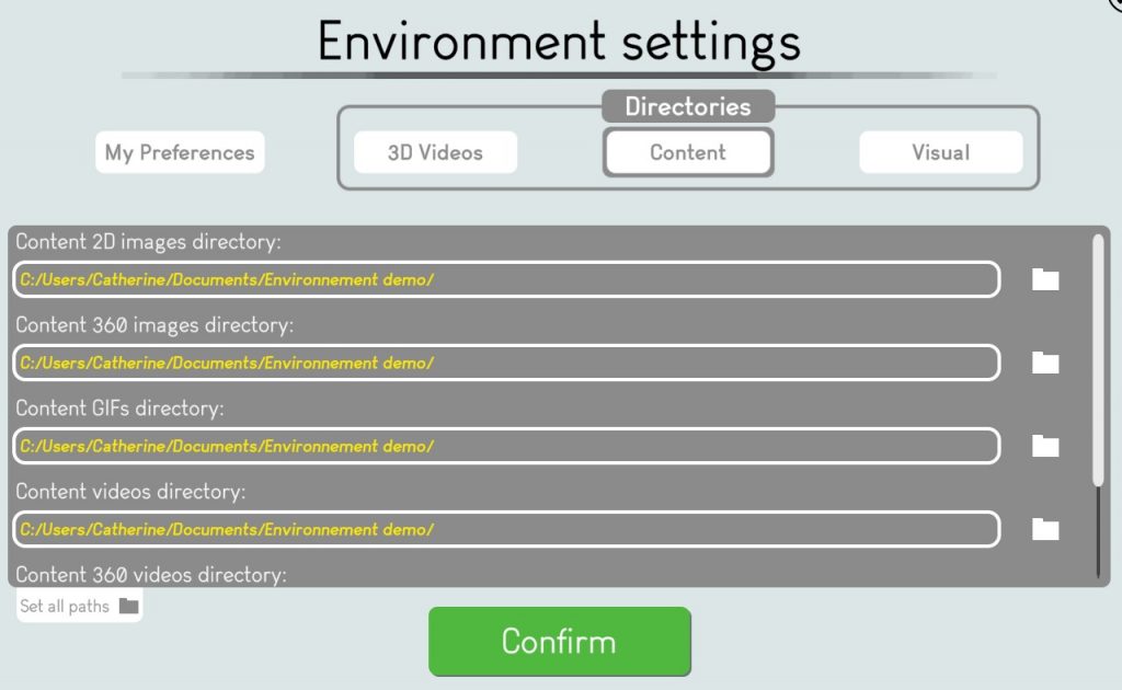
The Content section of the environment settings allows editing users to define the default directories where they will be able to select their content from when creating or editing a 2D or a 3D overlay.
For each type of content the editing user can define the exact path of the directory.
Instead of browsing their whole information system to select a content, an editing user accesses immediately the content list of the default directory.
The types of content that can be accessed from default directories are :
– 2D images
– 360 images
– GIF
– Videos
– 360 videos
– Documents: PDF, Word, XL
The default directories for content can be located on the same computer or on external servers or external drives.
Visual
Upon creating or editing a 2D or 3D overlay an editing user will select a type of representation and the representation itself.
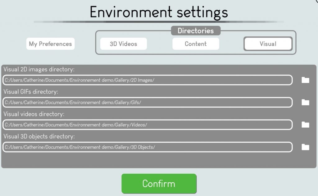
The Visual section of the environment settings allows editor users to define the default directories where they will be able to select their representation from when creating or editing a 2D or a 3D overlay.
For each type of representation the editing user can define the exact path of the directory.
Instead of browsing their whole information system to select a representation, an editing user accesses immediately the representations list of the default directory.

The types of representations that can be accessed from default directories are :
– 2D images
– GIF
– Videos
– 3D objects
The default directories for representations can be located on the same computer or on external servers or external drives.
Once all sections are updated the editor user can push the “Confirm” button” to start the new environment creation.

It generally takes a few minutes to create the environment, especially if it’s a copy of a large existing environment with lots of content.
Once the environment is created it will appear in the environments list.
The user will be able to open the environment and start editing it.
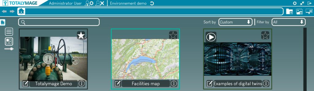
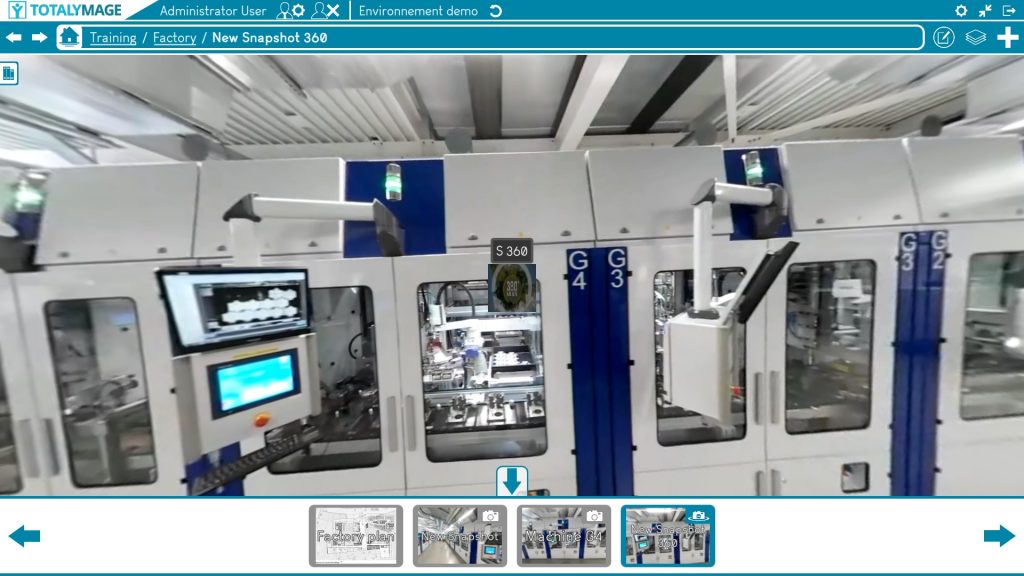
Environment main page
Upon selecting an environment in the environments management page and opening it, the environment main page is displayed.
An environment is a set of projects, dashboards and presentations.
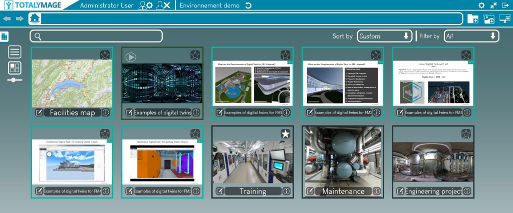
The environment main page displays on the top bar of the screen:

The logo
The logo is displayed at all times in the application in the upper left corner.
The logo is defined at the environment level.
An editor user can modify the logo in the environment settings in the “My Preferences” section.
It is also possible to define a single logo for a company for all environments.
This default logo needs to be defined in the assets of the TotalYmage application executable to become the default logo for the company.
An administrator user can to modify the default logo by importing a logo image (that needs to be called Applogo) to the following directory:
The name of the user
Upon login the user credentials are checked in the back-office.
The user is recognized and the TotalYmage application displays the name of the user.

The rights of the user
The rights of a user are defined by an Administrator user in the TotalYmage back-office.


An administrator user can give 3 different rights to access the TotalYmage applications and back-office:
Visitor:
A visitor user can access the back-office to download the latest releases and terms & conditions of the TotalYmage applications.
A visitor user can login to the TotalYmage application and navigate in any environment he has access rights to, click on the interactive content as a read-only user.
But a visitor user cannot modify any content in an environment.
Editor:
An editor user has all visitor user’s rights.
Moreover an editor user can login to the application and create and modify environments.
Administrator:
An administrator user has all editor user’s rights.
Moreover an administrator user can create and manage users, 360 and 3D videos in the back-office.
The editor who publishes an environment in the back-office can give rights to access to any user of the company.
A user who is given rights to access an environment is able to select the environment in the environments management page and to open it.
Upon opening an environment, the user can see the symbol of the rights he was given.
By clicking on the symbol a user can decrease this role from administrator to editor, or editor to visitor.
The button for the user to sign out
A user can at any time click on the “Sign out” button to go back to the login page.


The name of the environment
Upon selecting an environment in the environments list in the environments management page, a user can open the selected environment.
The name of the environment is displayed in the environment main page as soon as it is opened by the user.
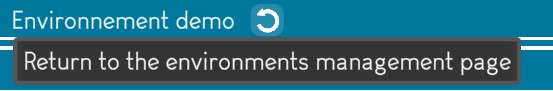
The Return to the environments management page button
A user can at any time close the open environment.
The user must click on the “Return to the environments management page” button.
The environments management page is then displayed.

The environment main page displays on the second row of the screen top bar:

Left arrow
The left arrow allows a user to come back to the previous screen.
Please note that this arrow just allows to navigate in the TotalYmage application, following the path of the previous actions.
This arrow does not undo changes in the content of the environment; for example the creation of an overlay or the deletion of a content.
Right arrow
The right arrow allows a user to go back to the next screen after using the left arrow.
Please note that this arrow just allows to navigate in the TotalYmage application, going back to the path of the previous actions.
This arrow does not redo changes in the content of the environment; for example the creation of an overlay or the deletion of a content.
The “Home” button
Whatever content of an environment is opened, a user can click at any time on the “Home” button to come back to the environment main page.
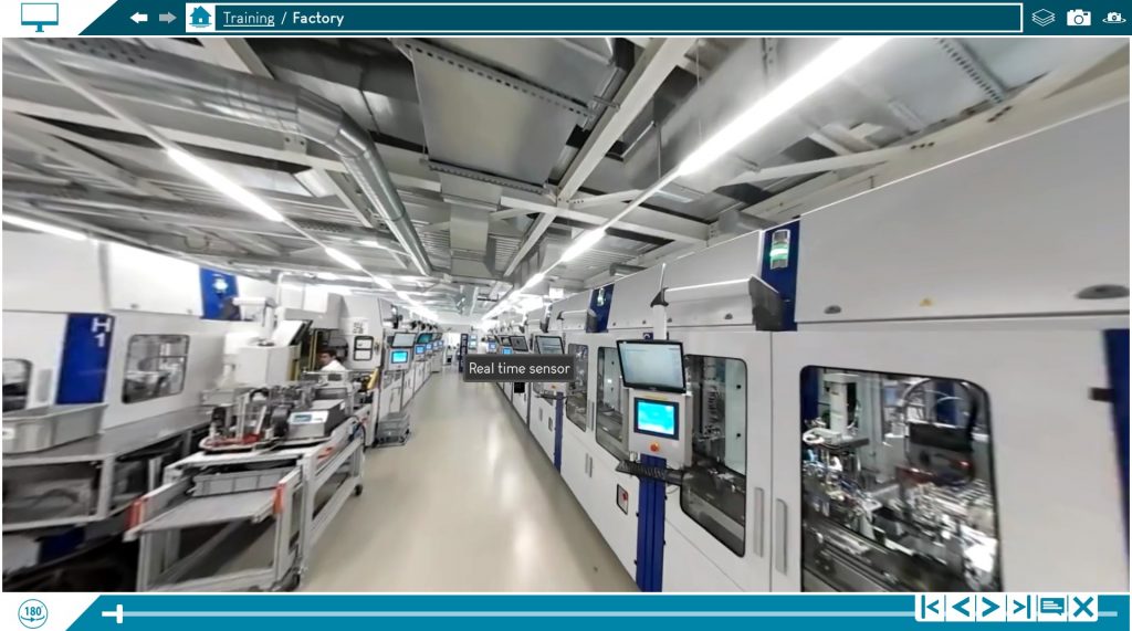
When a user navigates in the environment, opening projets, dashboards, content, you will always see the hierarchy of the content you opened on the right of the “Home” button.
If you point your mouse over any level of the hierarchy you see the type of the object; for example, a project, dashboard, scene, image, 360 photo, …

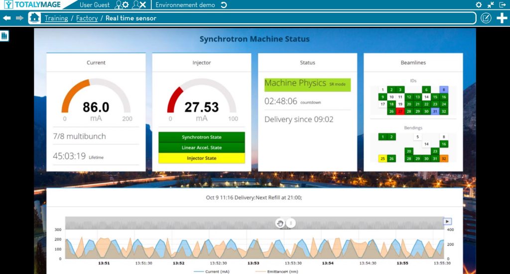
Level in the hierarchy
When a user navigates in an environment, opening projets, dashboards, content, it is important that the user knows at all times the level of the content in the hierarchy of the environment.
The level of a content in the hierarchy is defined by the succession of parent / child content on the right of the “Home” button.
Each hierarchy level is defined by its name and type.
The name is written as a link in the environment hierarchy.
The type is shown as a tooltip when the user points the mouse over the link or when the user touches the link on a touch screen.
The user can click on the Name link of any level in the hierarchy to teleport to the corresponding screen.
Hence the user is able to move one or several notches up in the hierarchy of the environment content.

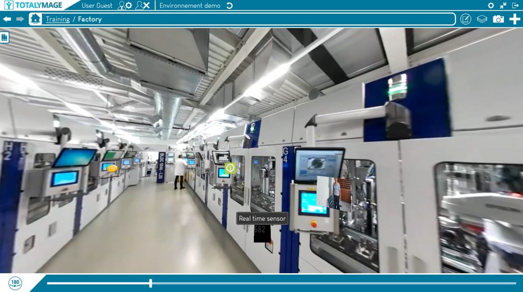
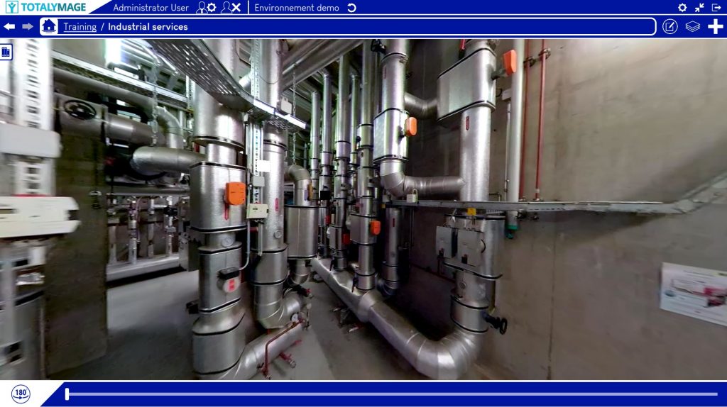
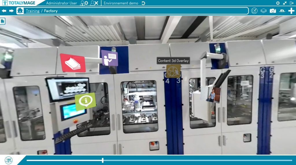
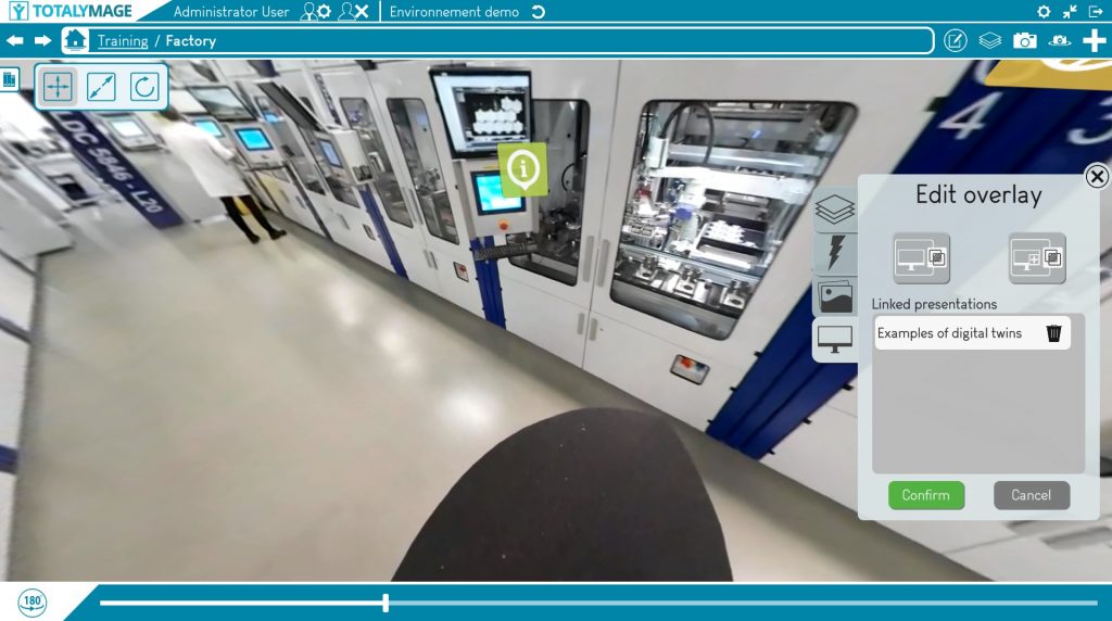
For example the “Real time sensor” dashboard is the content of an overlay in the “Factory” scene, itself in the “Training project” of the “Environment demo” environment.
Edition of the current open content
An editor user may edit any of the content of an environment.
When opened, a content is displayed at the center of the screen and its name and parents names are displayed in the hierarchy.
An editor user can at any time edit an open content by clicking on the “Edit” button on the right of the hierarchy links field.
The environment main page displays on the right of the screen top row:
My Preferences
A click on the “My preferences” button displays the user’s preferences.
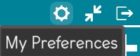
The user can access all options and define the preferred configuration.

General
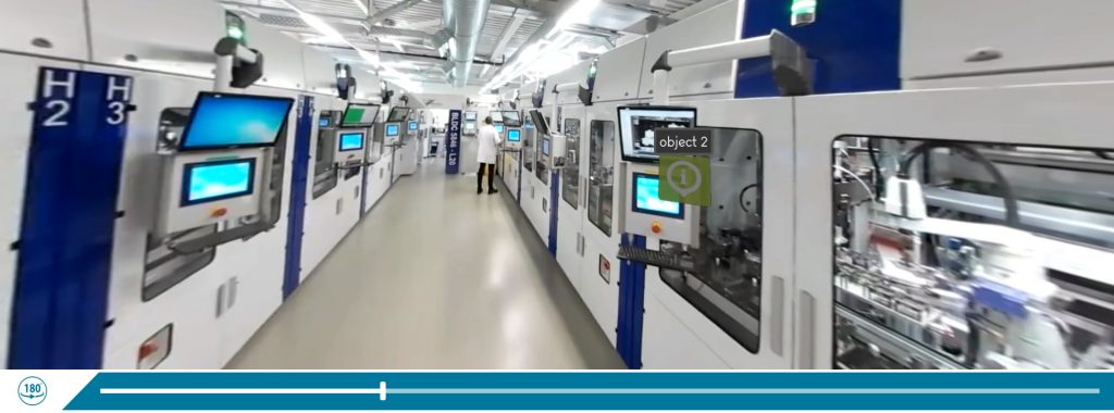
Display the scene’s slider

The slider is the object at the bottom of the screen when a user navigates in a scene.
The user can drag the slider to move in the continuous 360 images of the scene.
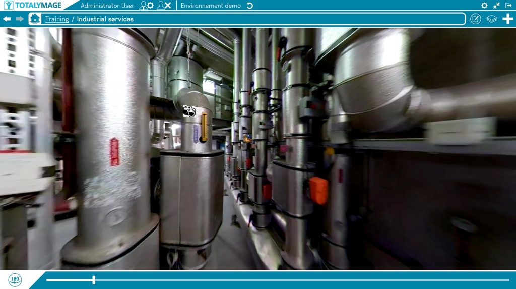
The user can click on the 180° button to look at the opposite direction in the 360 image.
This allows the user to turn quickly to the other side instead of turning around in the 360 image with the arrows or by dragging the 360 image to a half turn in the 360 image.

Check the box to display the slider and the 180° button.
It’s an interesting tool especially when working on a touch screen; it’s easy to click and drag without a keyboard nor a mouse.

Uncheck the box to display a bigger screen down to the bottom of the screen.
Display snapshots in a round presentation frame
Snapshots can be have two different designs :
- round
- rectangular

Check the box to display snapshots in a round design:

Uncheck the box to display snapshots in a rectangular design.
Display menu tooltips
About 100 menu buttons can be clicked on in the TotalYmage application.
To help the user know at any time what each button is for, there is the possibility to display tooltips when the user points the mouse over a button or when the user touches the button on a touch screen.

Nouvelle image avec nouvelle version
Check the box to display menu tooltips at all times.

Nouvelle image avec nouvelle version
Uncheck the box to hide the menu tooltips when clicking on a menu button or touching a menu button on a touch screen.
Please note that this option only covers the menu tooltips and doesn’t apply to the overlays tooltips.
The option to display or not the overlay tooltips is specific to an environment in the environment settings that can be accessed in the environments management page.
Open URL links in the default external browser
Upon double clicking on an overlay whose content is a web link, the TotalYmage application allows two ways to open the URL content.

Uncheck the box to open the URL content in a usual window of the TotalYmage application.
This option allows a user to access the web content and remain at all times in the TotalYmage application.
It allows to keep the TotalYmage efficiency switching from one tool to an other in the same application.

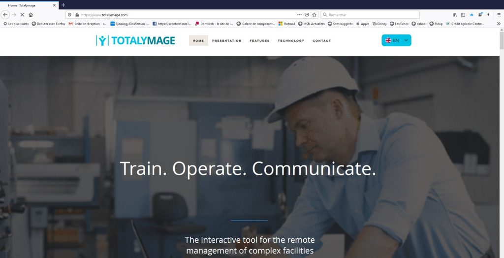
Check the box to open the URL content in the default external browser of the computer.
This option allows to keep several web pages open at the same time in an external navigator, for example to mark some of them as favorites for an access external to the TotalYmage application.
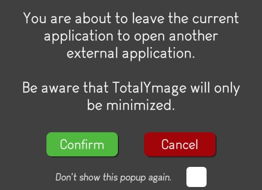
Upon opening the URL content in the default external browser, the following message is always displayed to the user.
The user has to click on the “Confirm” button to access the URL content in the external browser.
Beware that when this option is checked it allows a former user of the TotalYmage application to get access to a content the user may not be allowed to access any longer.
Use VSync
VSync is a technical option.
When a user runs the TotalYmage application on a server that doesn’t have any GPU nor graphic card, the VSync option provides the graphic capabilities to display the environments. Those graphic resources come from the machine CPU.

Check the box to allow a good balance between the CPU and graphic capabilities of the machine running the TotalYmage application.

Uncheck the box not to use the VSync balancing.
Camera direction influences playback direction
This option allows users to choose how the navigation in a scene should occur when users move back and forth in a scene.

Nouvelle photo avec nouvelle version
Check the box to allow the following behaviour:
The user moves forward in a scene by clicking on the “up” arrow”.
At the same time the user turns around in the images by clicking on the left or right arrow.
To the point when he continues to move forward by clicking on the “up” arrow but he is looking back.
If the user stops clicking on the “up” arrow and resumes clicking on the “up” arrow, the move forward goes back in the scene.

Nouvelle photo avec nouvelle version
Uncheck the box to allow the following behaviour:
The user moves forward in a scene by clicking on the “up” arrow”.
At the same time the user turns around in the images by clicking on the left or right arrow.
To the point when he continues to move forward by clicking on the “up” arrow but he is looking back.
If the user stops clicking on the “up” arrow and resumes clicking on the “up” arrow, the move forward in the scene continues in the same direction.
Scenes video play speeds
Users can navigate forward or backward in a scene by pushing the “up” or “down” arrow.
If they want to go quicker or slower while navigating forward or backward in the 360 video images, they can push the “1”, “2” or “3” key on the keyboard to switch to a different speed, .
This speed option allows a user to set the three pre-defined speeds at which the user will be able to navigate in any scene.

Each of the 3 speeds can be set to a number between 0,5 and 3.
A speed equal to 1,0 is equivalent to the speed of the 360 video capture if the user keeps pushing the “up” or “down” arrow.
To pre-define each of the default speeds, the user can drag the slider to the right number between 0,5 and 3.
Upon opening a scene the default speed is the Speed 1.
While moving forward or backward, the user can click on “2” on the keyboard to switch to Speed 2, on “3” to switch to Speed 3, or on “1” to switch back to Speed 1.
Language
Language
The user can choose the preferred language of the TotalYmage application menus between English, French and Chinese.

The user may check the box of either of the 3 available languages.
The choosen language only applies to the TotalYmage application menus, button, tooltips.
The choosen language doesn’t apply to the content names (environments, projects, dashboards, scenes, overlays, etc …), these content will remain in their original language.
Display
Top bar
The user can choose the way the top line of the screen appears.
There are two options for the top bar display:
Choose the “Fix” option to always show the top bar of the screen.
Choose the “Sliding” option to show the top bar only when needed.
The user can move the mouse to the upper part of the screen and the top bar will appear.
If the mouse is removed from the top bar perimeter the top bar will disappear automatically.
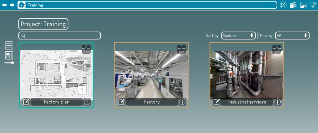
The “Sliding” option allows images to be displayed on a bigger portion of the screen, as the top bar doesn’t appear permanently.
But certain users dislike the sliding effect that they don’t control well.
Library opening mode
This option allows users to choose how to open and close the library.

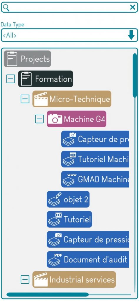
The library is the window on the left of the screen that allows to see the list, relationships and types of all the content of an environment.
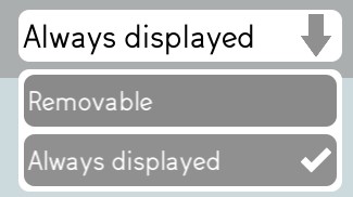
Photo de l’option Fix (sera ainsi dans la nouvelle version)
Choose the “Fix” option to allow the following behaviour:
The user clicks on the “Open the library” button to display the library window on the third left of the screen.
The clicks on the “Close the library” button to close the library window.
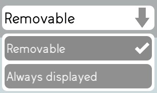
Photo de l’option Sliding (sera ainsi dans la nouvelle version)
Choose the “Sliding” option to allow the following behaviour:
The user points the mouse over the library symbol on the left of the screen and the library automatically opens in a window on the third left of the screen.
While the user keeps the mouse inside the library window perimeter the window remains opened.
When the user moves the mouse out of the library window perimeter the window closes itself automatically.
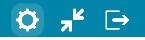
The “Windows mode” / “Full scene” button
A user can at any time respectively reduce and enlarge the application screen.
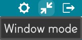
The “reduce” mode is especially used when the user needs to switch to an other application to retrieve some data or copy a URL for example.
The “full screen” mode allows the TotalYmage application to occupy the whole screen. The images are even more immersive.
The “Quit” button
To close the application

Please note that your preferences are not saved when you exit abruptly by closing the application using a different way; for example clicking on the Windows closing button when the application is not full screen, or killing the application through the task manager.
Closing the application with the “Quit” button performs the saving of the preferences to the back-office.
These preferences are retrieved when the user logs in.
On the second top right of the screen

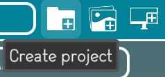
The Create project button
The “Create project” button allows an editor user to create a project of an environment.
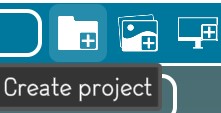
The process to create a project is explained in the “Project creation” section.
The Create dashboard button
The “Create dashboard” button allows an editor user to create a dashboard of an environment or a dashboard of a project.
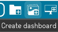
The process to create a dashboard is explained in the “Dashboard creation” section.
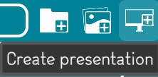
The Create presentation button
The “Create presentation” button allows an editor user to create a presentation of an environment or a presentation of a project.
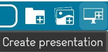
The process to create a presentation is explained in the “Presentation creation” section.
Project creation
An editor user is able to create projects on his own.
A project includes a set of scenes, dashboards and presentations.
Start the project creation
There are two ways to open the project creation window.
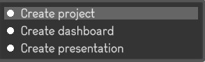
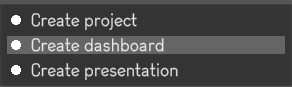
First way : Click on the “Create project” button
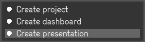
Second way : Click right at any place on the background of the environment main page, the following menu will be displayed.
And just click on the “Create project” link to start the project creation.
Write the name of the project
A name is compulsory to create a project.
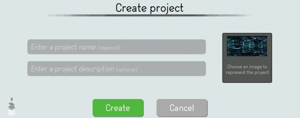
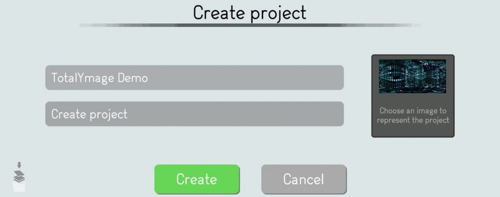
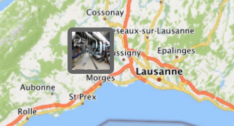
Choose an image to represent the project
It’s nicer in the environment main page to see specific pictures for the projects.
The editor user may click on the image thumbnail to access the image browser.
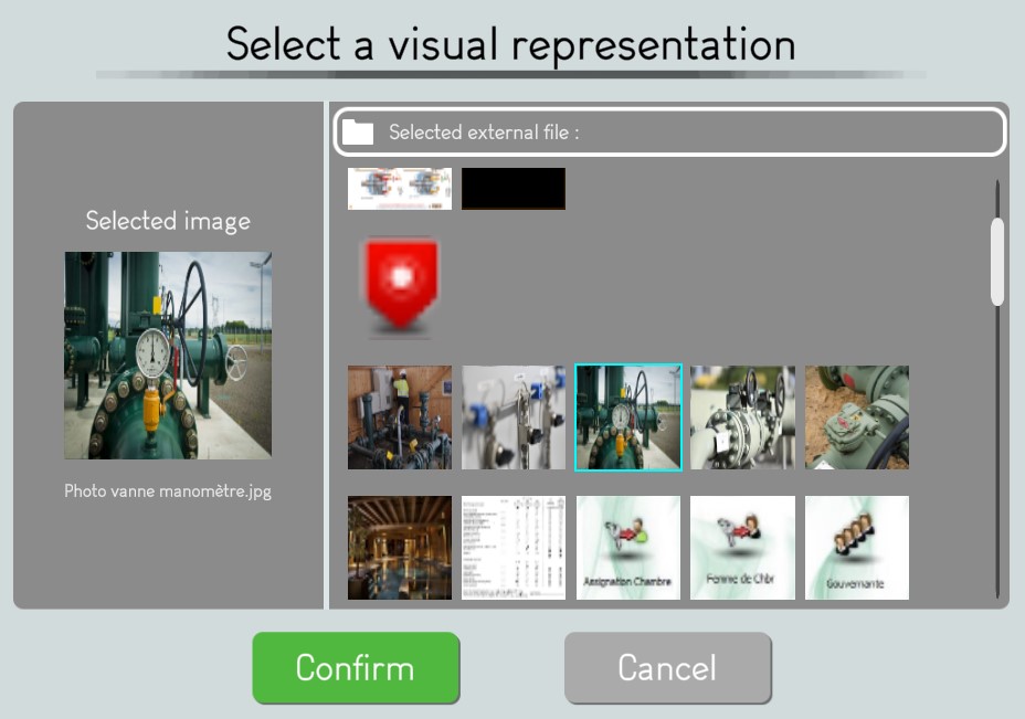
The editor user may browse and select a visual representation for the project.
Validate the project creation
The editor user has to click on the “Create” button to validate the creation of the project.
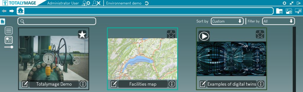
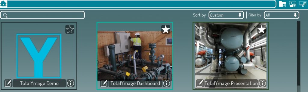
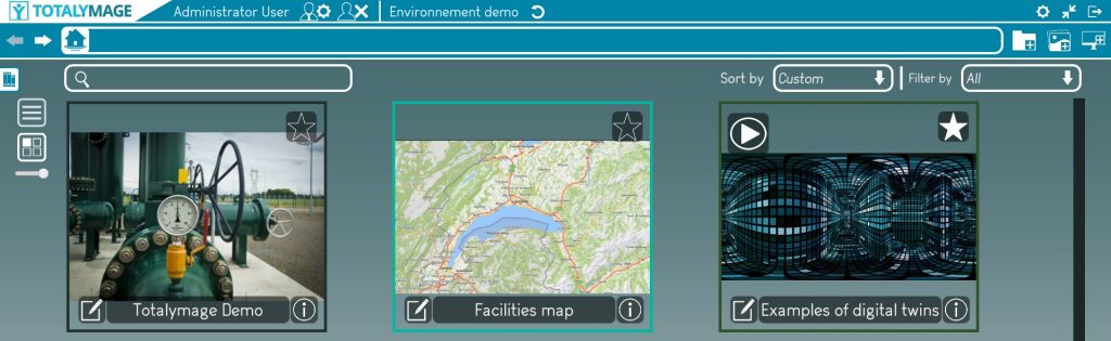
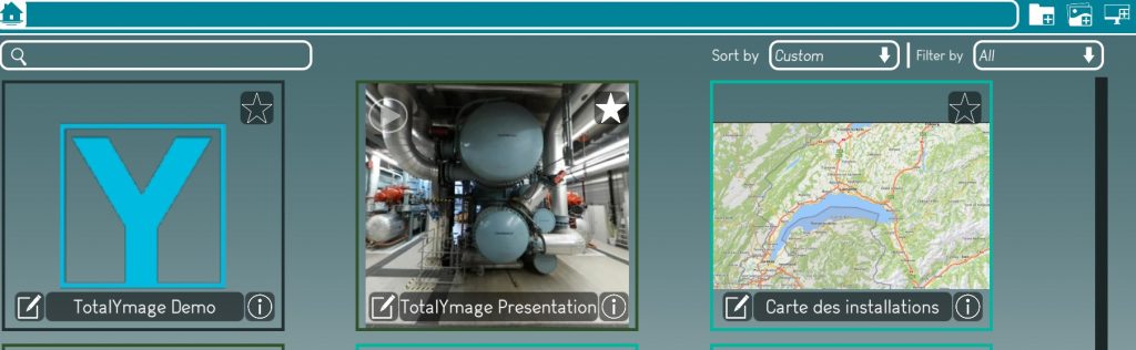
A project thumbnail appears with a black outline in the environment main page.
Once a project is created an editor user is able to create scenes, dashboards and presentations.
Environment Dashboard creation
An editor user is able to create dashboards on his own.
A dashboard can be created in an environment or in a project.
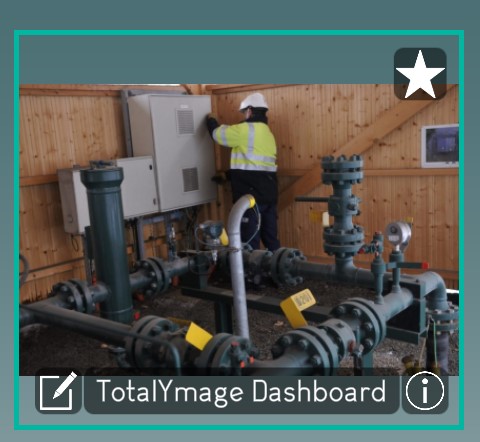
A dashboard is a single 2D image from a picture or a PDF, where an editor user can position a 2D overlay.
This allows a user to click on a 2D overlay on a dashboard to access a specific content.
Start the dashboard creation
There are two ways to open the dashboard creation window.
First way : Click on the “Create dashboard” button

Second way : Click right at any place on the background of the environment main page for an environment dashboard, or in a project page for a project dashboard, the following menu will be displayed.
And just click on the “Create dashboard” link to start the dashboard creation.
Write the name of the dashboard
A name is compulsory to create a dashboard.
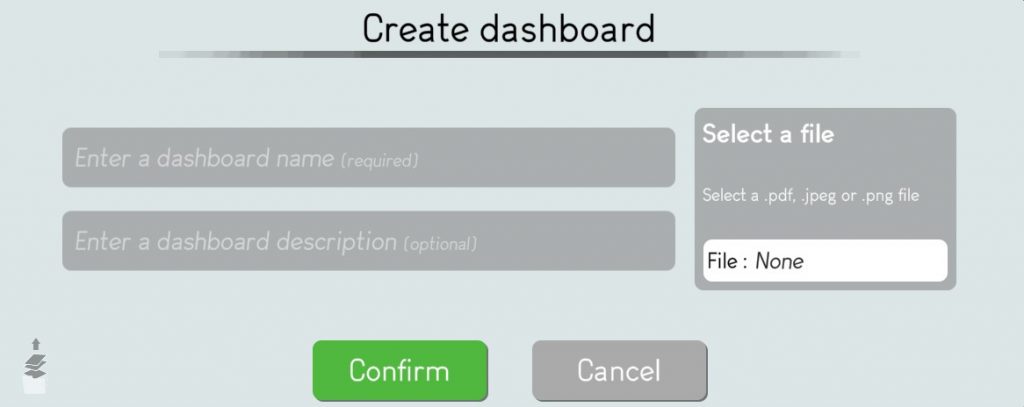
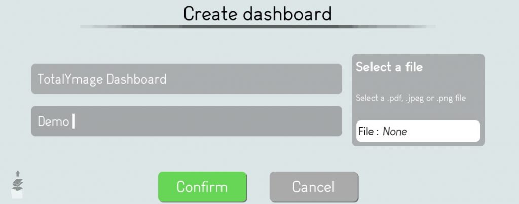
Choose a 2D image to represent the project
The editor user must upload the 2D image in .jpg, .jpeg, .png or a PDF.
The editor user may click on the “Select a file” section to access the image browser.
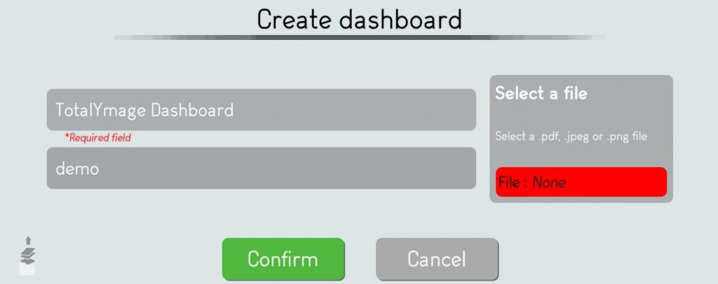
The editor user may browse and select the dashboard file.
Once selected the editor user must click on the “Ok” button to validate the file selection.
Validate the dashboard creation
The editor user has to click on the “Confirm” button to validate the dashboard creation.

A dashboard thumbnail appears as a light green outline in an environment main page and in a project page.
Once a dashboard is created an editor user is able to add 2D overlays or to link an existing 2D overlay with the dashboard.
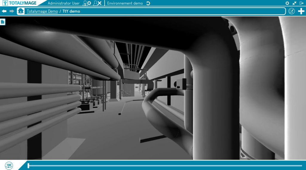
Scene creation
An editor user is able to create scenes in a project on his own.
A scene is a set of continuous 360 images extracted from a 360 video that has been analyzed by the TotalYmage algorithms to create a 3D model linked to theses images.
A scene allows users to navigate forward and backward, and to turn around in 360 degrees inside the 360 images.
Start the scene creation
There are two ways to open the scene creation window.
First way : Click on the “Create scene” button
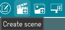
Second way : Click right at any place on the background of a project page, the following menu will be displayed.
And just click on the “Create scene” link to start the scene creation.

Write the name of the scene
A name is compulsory to create a scene.
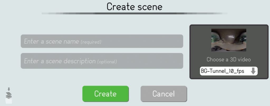
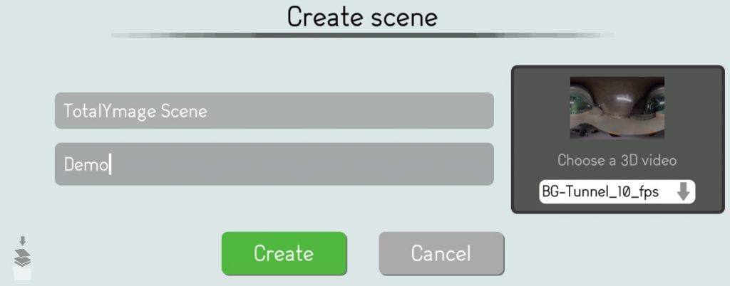
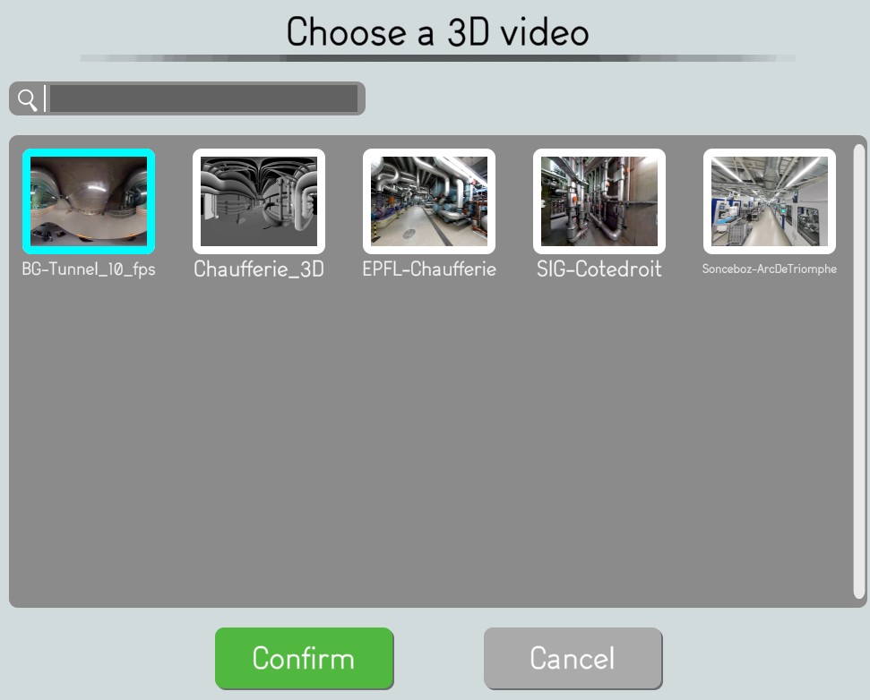
Choose a 3D Video
The editor user must click in the 3D videos list to choose a specific 3D video for the scene in creation.
The editor user must select a 3D video in the 3D videos list and click on the “Confirm” button.
Validate the scene creation
The editor user has to click on the “Create” button to validate the scene creation.
A scene thumbnail appears with a beige outline.
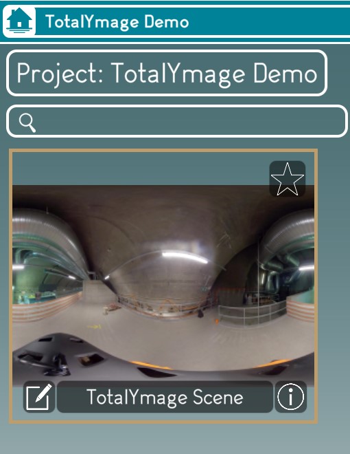
Once a scene is created the editor user is able to add 3D overlays in the scene, and to create snapshots and 360 snapshots.
This allows users to navigate in the scene and to interact with the 3D overlays of the scene.
Snapshot creation
An editor user is able to create snapshots in a scene on his own.
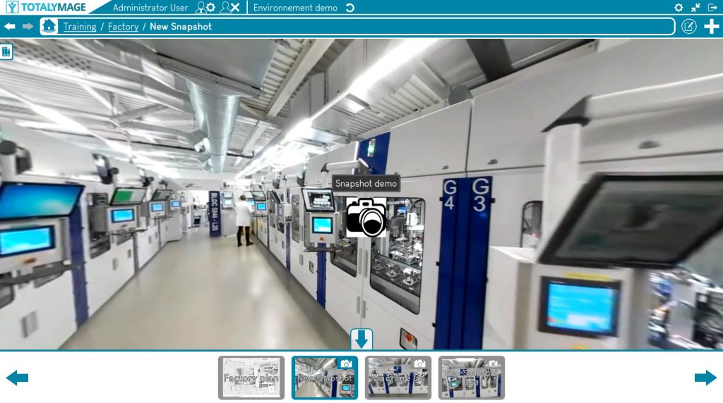
A snapshot is a 2D screen capture of a scene, that the user can create during its navigation in a scene.
A snapshot allows a user to access a favorite area of a scene.
Get to the snapshot view
An editor user may navigate in a scene towards a specific location.
The editor user may turn around in the 360 image to determine the right orientation for the snapshot before creating the snapshot.
Please note that this position and orientation can still be modified until the validation of the snapshot creation.
The editor user can write the name of the snapshot and move around in the images, find the right spot and the right orientation, before validating the snapshot creation.
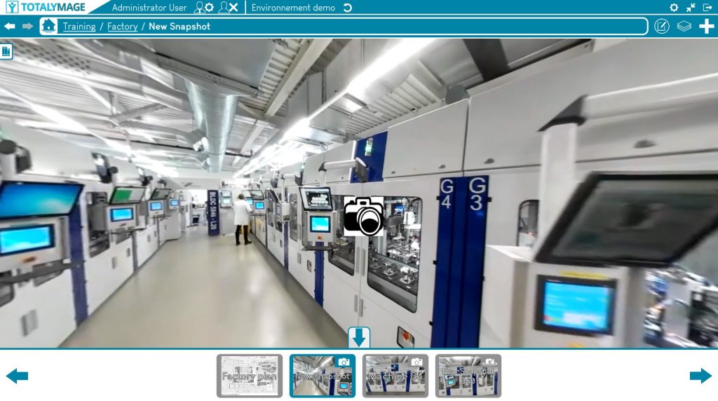
Create the snapshot
Once a position and an orientation are defined, there are two ways to open the snapshot creation window.
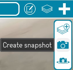
First way:
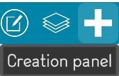
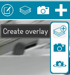
Click on the “+” button (creation panel) and then click on the “Create snapshot” button.

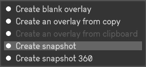
Second way: Click right at any place on the background of a scene, the following menu will be displayed.
And just click on the “Create snapshot” link to start the snapshot creation.
Write the name of the snapshot
A name is compulsory to create a snapshot.
The editor user must write the name of the snapshot.
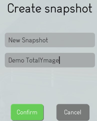
Validate the snapshot creation
The editor user has to click on the “Confirm” button to validate the snapshot creation.
The validation saves the current position and orientation of the screen.
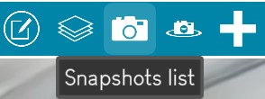
Access a snapshot
Once created a user can access any snapshot of a scene by clicking on the “Snapshots list” button to show the list of the existing snapshots for the scene.
The user can click on a snapshot from the list to open it.
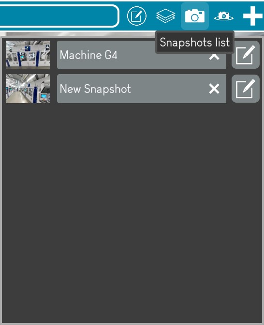
Upon opening a snapshot, the user gets teleported to its location.
A snapshot is just an image and the user cannot move around in the image even though this is an image snapshot from a scene.
While in a snapshot if the user wants to navigate in the scene in the area of the snapshot location, the user just needs to click on the Scene link in the environment hierarchy.

The dashboards and snapshots carousel is displayed at the bottom of the screen.
A user can teleport to any other dashboard, snapshot or snapshot 360.
While in a dashboard or a snapshot or a snapshot 360, a user can click on the Space bar of the keyboard or on the carousel arrow to hide or show the carousel.
Once a snapshot is created an editor user is able to add 2D overlays on the snapshot.
Snapshot 360 creation
An editor user is able to create snapshots 360 in a scene on his own.
A snapshot 360 is a 360 image of a scene, that the user can create during its navigation in a scene.
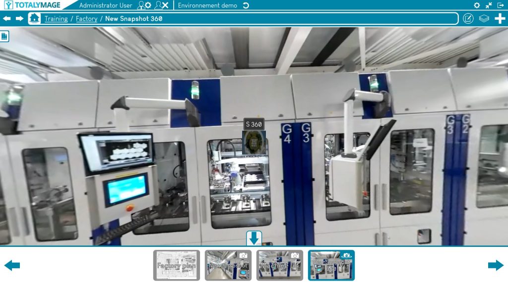
A snapshot 360 allows a user to access a favorite area of a scene.
Get to the snapshot 360 view
An editor user may navigate in a scene towards a specific location.
The editor user may turn around in the 360 image to define the right orientation.
This defined orientation is just the initial orientation when the visitor user accesses the snapshot 360. The visitor user is able to turn around in the snapshot 360 at any time.
Please note that the orientation can be modified until the validation of the snapshot 360 creation.
The editor user can write the name of the snapshot and move around in the images, find the right spot and the right initial orientation, before validating the snapshot 360 creation.
Create the snapshot 360
There are two ways to open the snapshot 360 creation window.
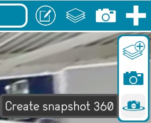
First way:
Click on the “+” button (creation panel) and then click on the “Create snapshot 360” button.

Second way: Click right at any place on the background of a scene, the following menu will be displayed.
And just click on the “Create snapshot 360” link to start the snapshot 360 creation.
Write the name of the snapshot 360
A name is compulsory to create a snapshot 360.
The editor user must write the name of the snapshot 360.
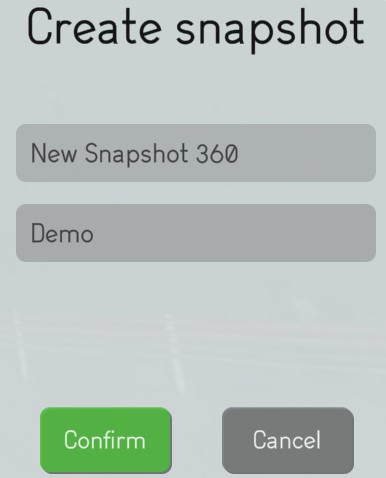
Validate the snapshot 360 creation
The editor user has to click on the “Confirm” button to validate the snapshot 360 creation.
The validation saves the current position and orientation of the screen.
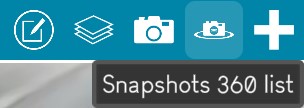
Access the snapshot 360
Once created a user can access any snapshot 360 of a scene by clicking on the “Snapshots 360 list” button to show the list of the existing snapshots 360 for the scene.
The user can click on a snapshot 360 from the list to open it.
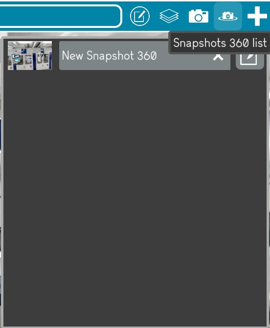
Upon opening a snapshot 360, the user gets teleported to its location with its initial orientation.
The user can look around in the 360 image with the arrows or by dragging the screen with a finger on a touch screen.
A snapshot 360 is just a 360 image and the user cannot move around in the 360 image even though this is a 360 photo of the scene.
While in a snapshot 360 if the user wants to navigate in the scene from the area of the snapshot 360 location, the user just needs to click on the Scene link in the environment hierarchy.

The dashboards and snapshots carousel is displayed at the bottom of the screen.
A user can teleport to any other dashboard or snapshot or snapshot 360.
While in a dashboard or a snapshot or a snapshot 360, a user can click on the “Space” bar of the keyboard or on the carousel arrow to hide or show the carousel.
Once a snapshot 360 is created an editor user is able to add 2D overlays on the snapshot 360.
3D overlay creation
An editor user is able to create 3D overlays in a scene.
A 3D overlay is an object positioned with 3D coordinates in a scene.
It is stable in a range of consecutive 360 images of the scene.

Pour un gif, l’idée était de ne mettre que la partie de 2 secondes montrant une surcouche quand on avance dans la scène.
Start the 3D overlay creation
There are three ways to create a 3D overlay in a scene:
First way:
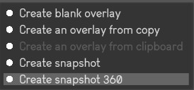
Click on the “+” button (creation panel) and then click on the “Create overlay” button.
Second way:
Click right on the “create blank overlay” button
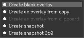
Third way:
Click right on the “create overlay from copy” button
This functionality allows to copy and paste an existing 2D or 3D overlay of the environment.

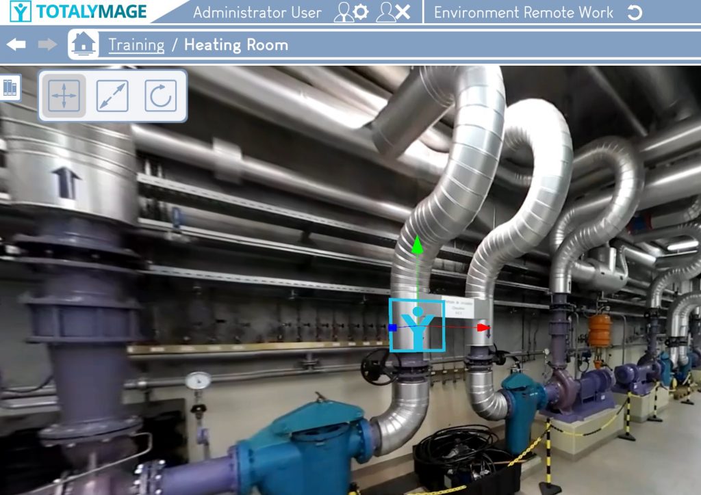
Select the position for the 3D overlay
Upon starting the 3D overlay creation, the vectorization points are displayed in the scene.
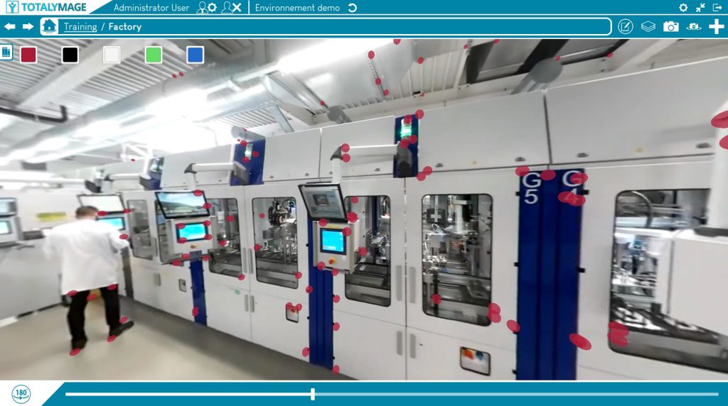
The editor user can navigate in the images of the scene and turn around in the 360 images to visualize the vectorization points next to the target position of the 3D overlay.
The editor user can click on one of the vectorization points to position the 3D overlay.
The 3D overlay is then defined by 3D coordinates in the scene.
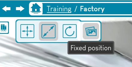
The 3D overlay appears on a fixed position when the user navigates in the continuum of 360 images of the scene.
Visitor users will be able to teleport directly to the 3D overlay.
Upon selecting one vectorization point (red points on the screen), the position of the 3D overlay can be changed using the translation arrows.
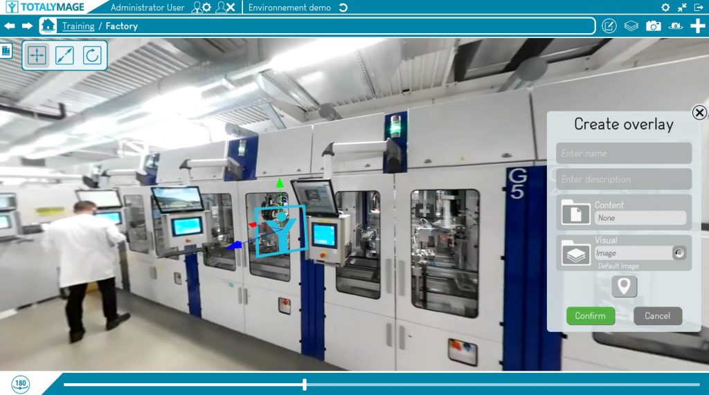
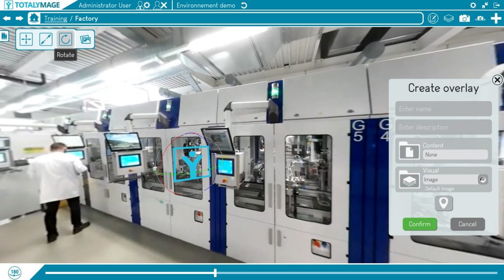
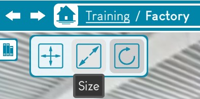
The 3D overlay can be rescaled by clicking on the “…” button
The 3D overlay representation can be rotated
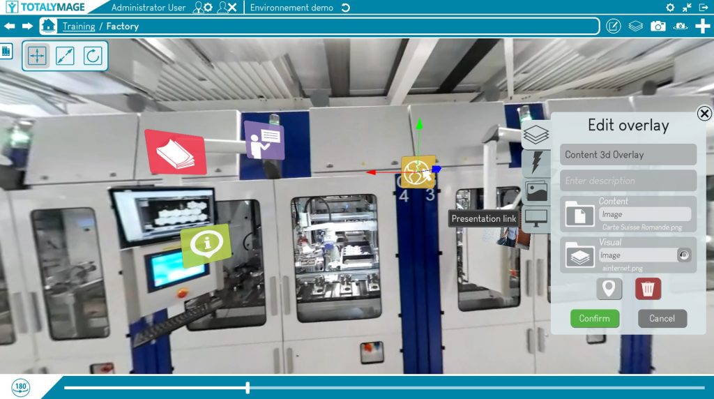
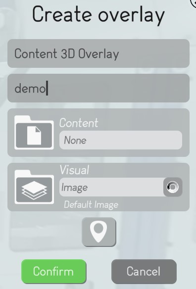
Upon clicking on one vectorization point, the “Create overlay” window is displayed.
Write the name of the 3D overlay
A name is compulsory to create a 3D overlay.
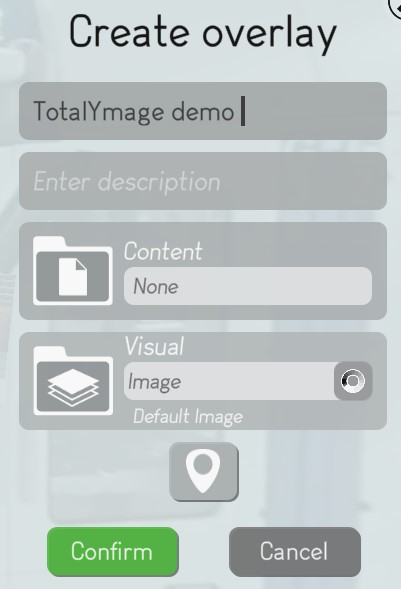
Choose a content for the 3D overlay
An editor user may create a content for the 3D overlay.
This is a content that is displayed when users double click on the 3D overlay representation.
Result
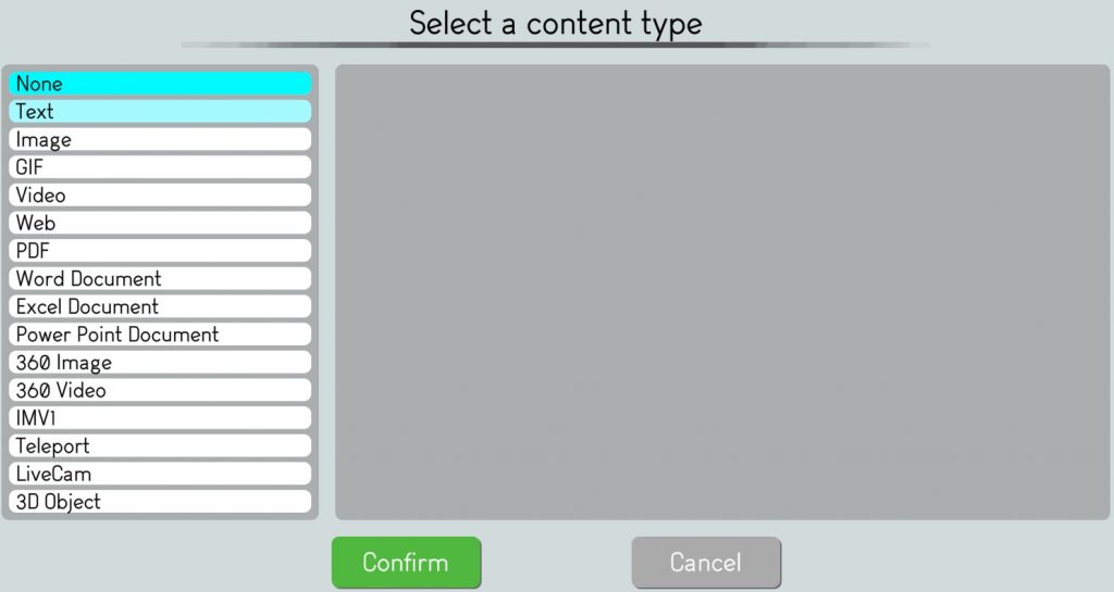
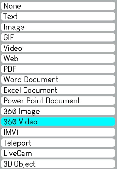
The editor user may click on a type of content for the 3D overlay:
– Text : the user can write a text in an editor
– 2D image : the user can upload a .jpg, .jpeg, .png format image
– Gif : the user can upload a .gif format file
– Video : the user can upload a .mp4, .mov, .m4v, .avi, .mkv, .ts, .webm, .flv, .vob, .ogg, .ogv, . mpg, .wmv, .3gp format file
– 360 image : the user can upload a .jpg, .jpeg, .png format image
– 360 video : the user can upload a .mp4, .mov, .m4v, .avi, .mkv, .ts, .webm, .flv, .vob, .ogg, .ogv, . mpg, .wmv, .3gp format file
– 3D object : the user can upload a .obj, .gltf, .glb format file
– Word : the user can upload a .doc, .docx format file
– Excel : the user can upload a .xls, .xlsx format file
– Powerpoint : the user can upload a .ppt, .pptx format file
– PDF : the user can upload a .pdf format file
– Teleport : the user can choose an existing content (project, dashboard, scene, snapshot, snapshot 360, overlay) to teleport to when double clicking on the representation
– IMV1 : 360 video live camera connection – on demand
– Basler : live production line camera connection – on demand
When choosing a content type requiring a file selection, the editor user may click on a predefined file in the default directory of the selected type of content.
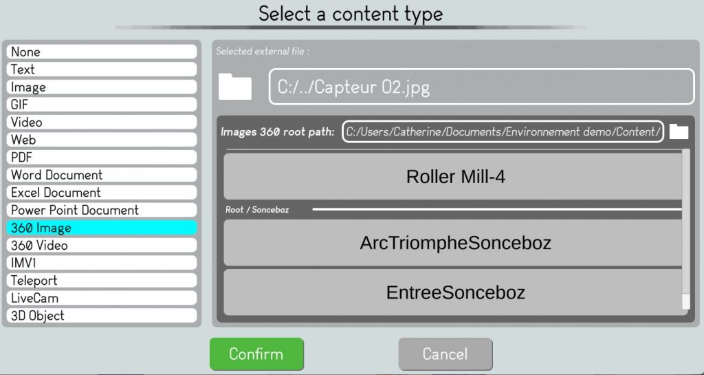
Or the editor user can browse the information system to select the right content file.
The editor user needs to click on the “Confirm” button to validate the representation selection.
Choose a representation for the 3D overlay
An editor user may create a 2D or 3D representation for the 3D overlay. This is a 2D or 3D object on which users can double click to access the 3D overlay content.
The editor user may click on a type of representation for the 3D overlay:
– Text : the user can write a text in a text editor
– 2D image : the user can upload a .jpg, .jpeg, .png format image
– Gif : the user can upload a .gif format file
– Video : the user can upload a .mp4, .mov, .m4v, .avi, .mkv, .ts, .webm, .flv, .vob, .ogg, .ogv, . mpg, .wmv, .3gp format file
– 3D object : the user can upload a .obj, .gltf, .glb format file
When choosing a type requiring a file selection, the editor user may click on a predefined file in the default directory of the selected type of representation.
Or the editor user can browse the information system to select the right representation file.
The editor user needs to click on the “Confirm” button to validate the representation selection.
Edit the position, size, orientation of the 3D overlay
The editor user may change the position of the 3D overlay representation by selecting an other vectorization point.
The editor user has to click on the ÉÉ button.
The editor user may change the size of the 3D overlay representation
An editor user has to click on the “Create” button to validate the 3D overlay creation.
When choosing a type requiring a file selection, the editor user may click on a predefined file in the default directory of the selected type of representation.

Or the editor user can browse the information system to select the right representation file.
The editor user needs to click on the “Confirm” button to validate the representation selection.
The user must give it a name. The user will navigate in the scene’s 360 images, will choose a 360 image and will choose an initial orientation of the view that users will have when accessing the 3D overlay.
The representation of the 3D overlay will appear in the overlays list on the top right menu of the scene page.
Once a 3D overlay is created, the user may create 2D overlays in its content (except for 3D object, Word, Excel, Powerpoint and Basler).
2D overlay creation in 2D images
An editor user is able to create 2D overlays in 2D images (images, dashboards, snapshots), and in any 3D overlay content (except for 3D object, Word, Excel, Powerpoint and Basler).
A 2D overlay can be positioned with 2D coordinates in a 2D image.
In a 2D image, the user can click on the ‘Create an overlay’ button.
The user must give it a name.
The user may choose a 2D representation (3D representations are not allowed for 2D overlays). This is the object that users see when they access the 2D image.
By default the 2D representation is the TotalYmage icon.
There are several types of representations :
– Text : the user can write a text in an editor
– 2D image : the user can upload a .jpg, .jpeg, .png format image
– Gif : the user can upload a .gif format file
– Video : the user can upload a .mp4, .mov, .m4v, .avi, .mkv, .ts, .webm, .flv, .vob, .ogg, .ogv, . mpg, .wmv, .3gp format file
The user may choose a content ; this content will be displayed when double clicking on the 2D overlay representation in the scene.
The user needs to choose a type of content :
– Text : the user can write a text in an editor
– 2D image : the user can upload a .jpg, .jpeg, .png format image
– Gif : the user can upload a .gif format file
– Video : the user can upload a .mp4, .mov, .m4v, .avi, .mkv, .ts, .webm, .flv, .vob, .ogg, .ogv, . mpg, .wmv, .3gp format file
– Word : the user can upload a .doc, .docx format file
– Excel : the user can upload a .xls, .xlsx format file
– Powerpoint : the user can upload a .ppt, .pptx format file
– PDF : the user can upload a .pdf format file
– Teleport : the user can choose an existing content (project, dashboard, scene, snapshot, snapshot 360, 2D overlay, 3D overlay) to teleport to when double clicking on the representation
– IMV1 : 360 video live camera connection – on demand
– Basler : live production line camera connection – on demand
The user will then validate the creation of the 2D overlay.
The representation of the 2D overlay will appear in the overlays list on the top right menu of the scene page.
Once a 2D overlay is created, the user may create 2D overlays in its content (except for 3D object, Word, Excel, Powerpoint and Basler).
2D overlay creation in 360 images and 360 videos
An editor user is able to create 2D overlays in spheric images.
A 2D overlay is can be positioned with 2D coordinates in a spheric image (360 photo, 360 video, snapshot 360, IMV1).
In a spheric image, the user can click on the ‘Create an overlay’ button.
The user must give it a name.
The user will choose the position of the 2D overlay representation in the sphere by rotating the image around the central position of the 2D overlay representation, or by using the 3D axis to translate the 2D representation in the sphere.
The user may choose a 2D representation (3D representations are not allowed for 2D overlays). This is the object that users see when they access the spheric image or when they teleport to the 2D overlay.
By default the 2D representation is the TotalYmage icon.
There are several types of representations :
– Text : the user can write a text in an editor
– 2D image : the user can upload a .jpg, .jpeg, .png format image
– Gif : the user can upload a .gif format file
– Video : the user can upload a .mp4, .mov, .m4v, .avi, .mkv, .ts, .webm, .flv, .vob, .ogg, .ogv, . mpg, .wmv, .3gp format file
The user may choose a content that will be displayed when double clicking on the 2D overlay representation in the scene.
The user needs to choose a type of content :
– Text : the user can write a text in an editor
– 2D image : the user can upload a .jpg, .jpeg, .png format image
– Gif : the user can upload a .gif format file
– Video : the user can upload a .mp4, .mov, .m4v, .avi, .mkv, .ts, .webm, .flv, .vob, .ogg, .ogv, . mpg, .wmv, .3gp format file
– Word : the user can upload a .doc, .docx format file
– Excel : the user can upload a .xls, .xlsx format file
– Powerpoint : the user can upload a .ppt, .pptx format file
– PDF : the user can upload a .pdf format file
– Teleport : the user can choose an existing content (project, dashboard, scene, snapshot, snapshot 360, 2D overlay, 3D overlay) to teleport to when double clicking on the representation
– IMV1 : 360 video live camera connection – on demand
– Basler : live production line camera connection – on demand
The user will then validate the creation of the 2D overlay.
The representation of the 2D overlay will appear in the overlays list on the top right menu of the spheric image.
Once a 2D overlay is created, the user may create 2D overlays in its content (except for 3D object, Word, Excel, Powerpoint and Basler).
Presentation creation
An editor user is able to create presentations on his own.
A presentation can be created in an environment or in a project.
A presentation is a set of interactive slides that the user will be able to present.
Start the presentation creation
There are two ways to open the presentation creation window.
First way : Click on the “Create presentation” button
Second way : Click right on the “Create presentation” link
Write the name of the presentation
A name is compulsory to create a presentation.
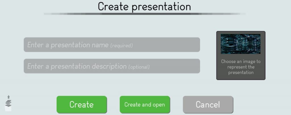
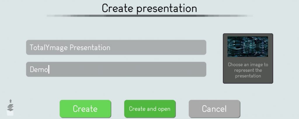
Choose an image to represent the presentation
It’s nicer in the environment main page to see specific pictures for each presentation.
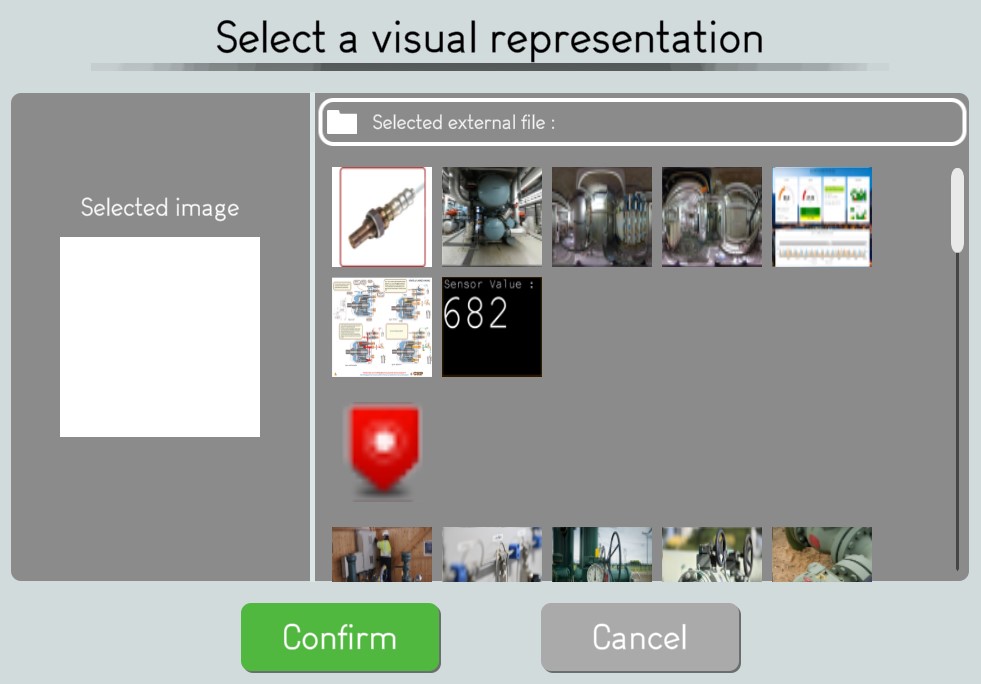
The editor user may click on the image thumbnail to access the image browser.
The editor user may browse and select a visual representation for the presentation.
Validate the presentation creation
The user has to click on the “Create” or “Create and Open” button to validate the creation of the presentation.
A presentation thumbnail appears with a dark green outline.
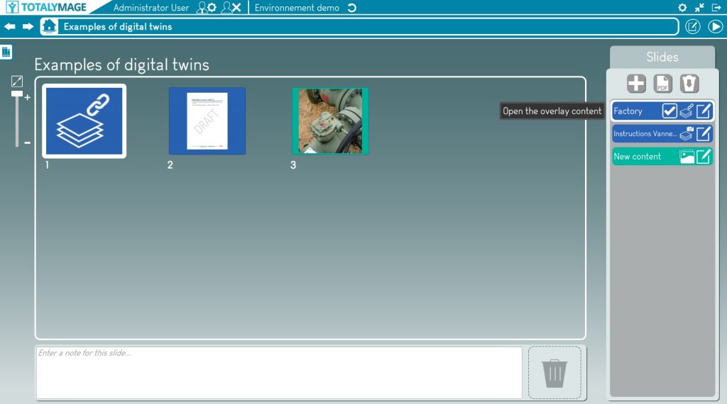
Presentation edition
Once a presentation is created, an editor user is able to create and manage slides in the presentation, using existing environment content and external content to make the presentation both interactive and immersive with clickable content in 360 images.
Create slides in a presentation
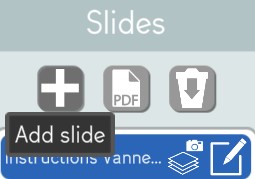
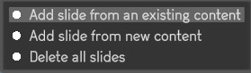
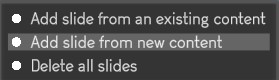
There are 3 ways to add slides in a presentation.
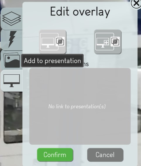
Add slide from an existing content
An editor user can add a slide to a presentation from an existing content of the environment.
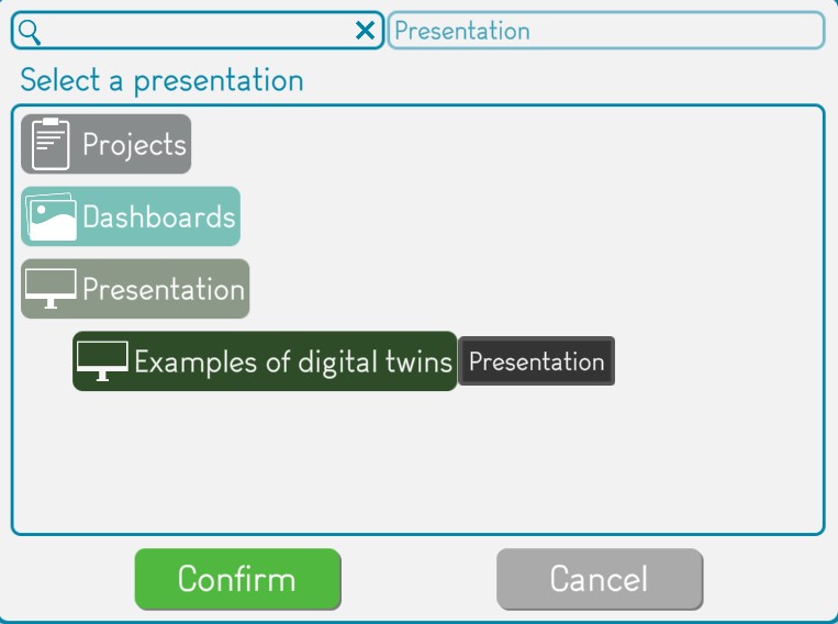
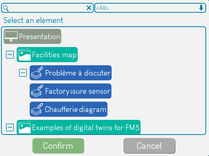
The editor user must click on the “Add slide” button and then on the “Add slide from an existing content” button.
The editor user must select an existing content of the environment from the library and click on “Confirm”.
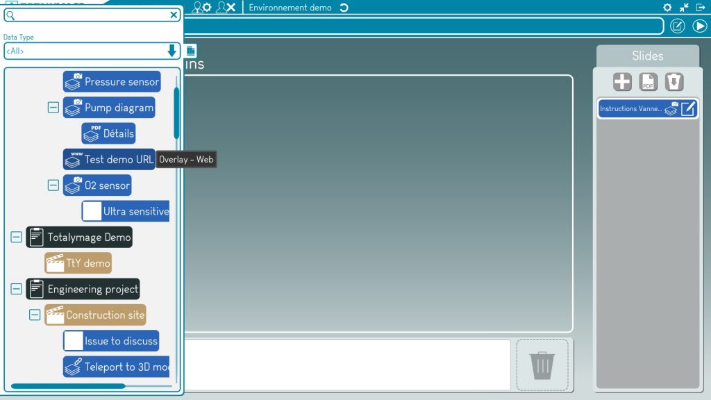
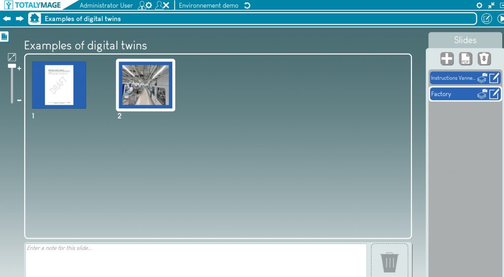
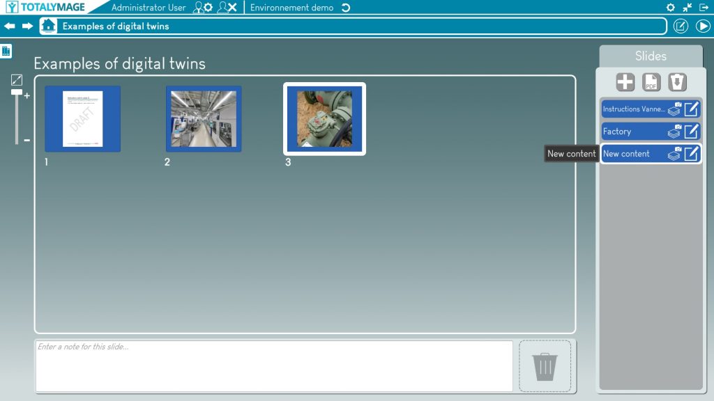
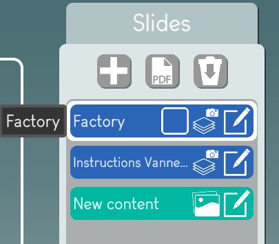
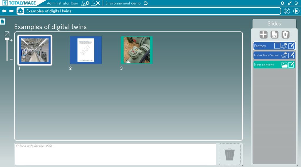
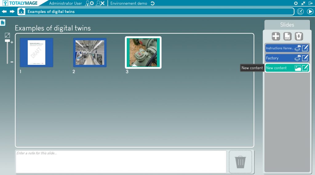
A new slide containing the selected content will be positioned as the latest slide of the presentation, both in the slide thumbnails area (in the center of the screen) and in the slide selection area (the vertical slides list on the right of the screen).
Add slide from new content
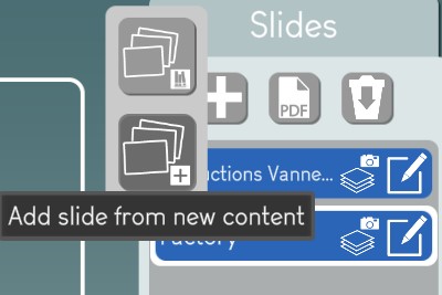
An editor user can add a slide with a new content to a presentation.
The editor user must click on the “Add slide” button and then on the “Add slide from new content” button.
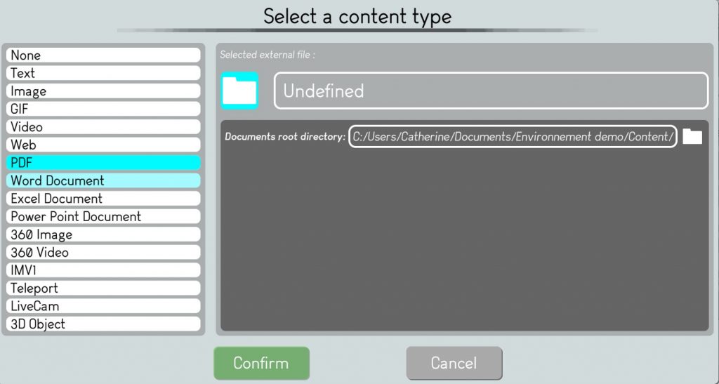
The editor user must enter the name of the new content, and must click of the content field to select a content type, browse the directories to select a file and click on the “Confirm button to validate the new content.
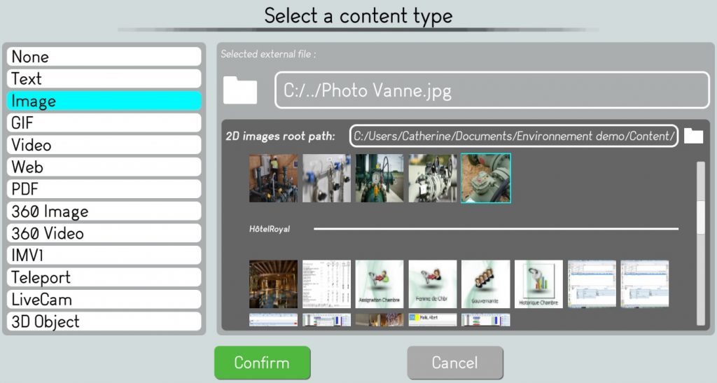
The editor user must click on “Confirm” to validate the new slide.
A new slide containing the new content will be positioned as the latest slide of the presentation, both in the slide thumbnails area (in the center of the screen) and in the slide selection area (the vertical slides list on the right of the screen).
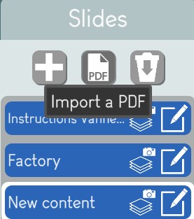
Import a PDF
An editor user can add the slides of an existing PDF to a presentation.
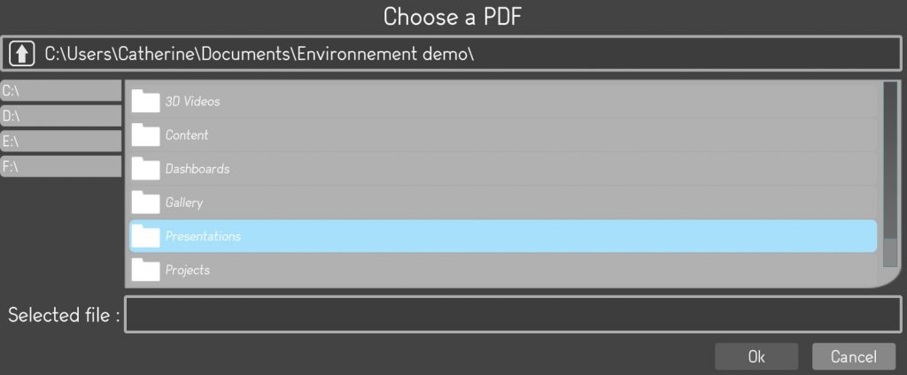
The editor user must click on the “Import a PDF” button and then must choose an existing PDF by browsing the directories.
Upon selecting a PDF file and clicking on the “OK” button, the PDF slides are created at the end of the presentation, both in the slide thumbnails area (in the center of the screen) and in the slide selection area (the vertical slides list on the right of the screen).
Modify a slide in a presentation
Once a slide is created in a presentation, an editor user can modify the slide.
If the slide references a 3D overlay, the default display of the slide is the scene view in front of the 3D overlay.
Result
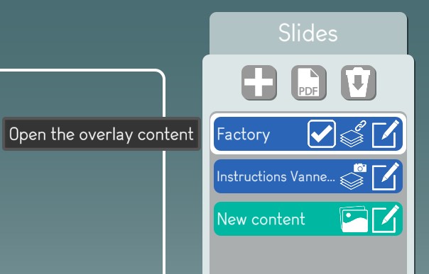
But it is also possible to display directly the content of the 3D overlay in the slide.
The editor user must check the “Teleport to overlay” check box in the vertical slides list.
Result
An editor user may also modify the content of a slide from the vertical slides list on the right of the presentation editor screen.
The editor user has to click on the “Edit” button to modify the content of the slide.
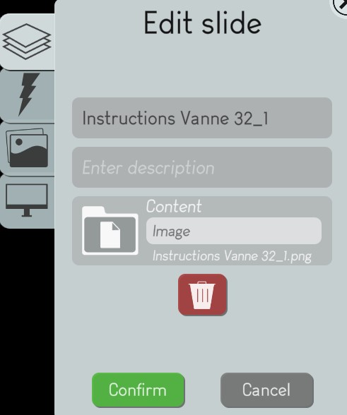

The editor user can change any characteristics of the slide content.
It is important to understand that modifying the content of a slide created from an existing content will modify the content itself, not only in the presentation, but also in the project it belongs to.
Convert a slide to a dashboard
Once a PDF file is imported in a presentation, its slides have an Image format and an editor user can convert any slide to a Dashboard format.
This functionality allows an editor user to transform each slide of a plain PDF into an interactive dashboard.
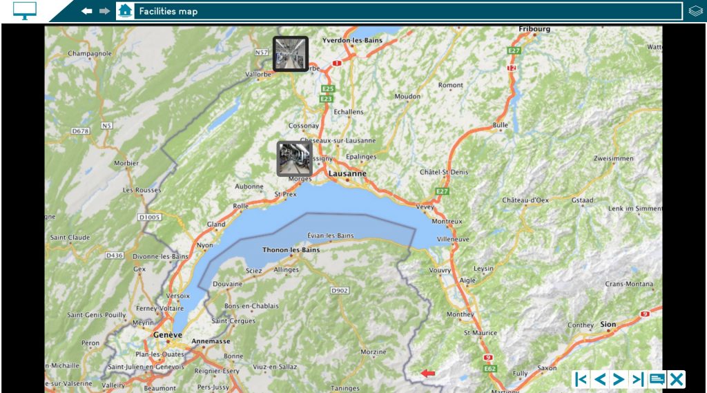
Hence a PDF presentation becomes an interactive presentation where slides are enriched with links to digital content including all environment content.
The editor user may select a slide of the presentation on the slide thumbnails area in the center of the presentation editor screen.
The editor user has to click right on the “Convert slide” button.
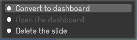
This changes the PDF slide into a dashboard with a light green outline.
Open and enrich the dashboard
Upon converting a PDF slide to a dashboard slide, the editor user may click right on the slide thumbnail and click on the “Open dashboard” link.
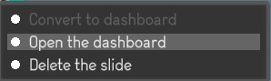
The dashboard slide is then displayed and the editor user is able to create 2D overlays in the dashboard.

Play a presentation
Any user can play an existing presentation.
There are 3 ways to play a presentation:
Click on the “Play” button of the presentation thumbnail in the environment main page or the project page.
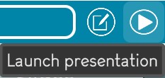
Click on the “Play” button in the presentation editor screen.
Double click on a slide thumbnail in the presentation editor to start the presentation from that slide.